eHouse WiFi Smart Home consists of small all-in-one controllers containing on board drivers and relays for direct control of:
- any electrical devices (on off)
- LED lights (dimming)
- 230V power supply
- Infrared receiver/transmitter
- Temperature sensor (-50,+50C)
Some resources are optional and some can be installed only on PCB manufacture state.
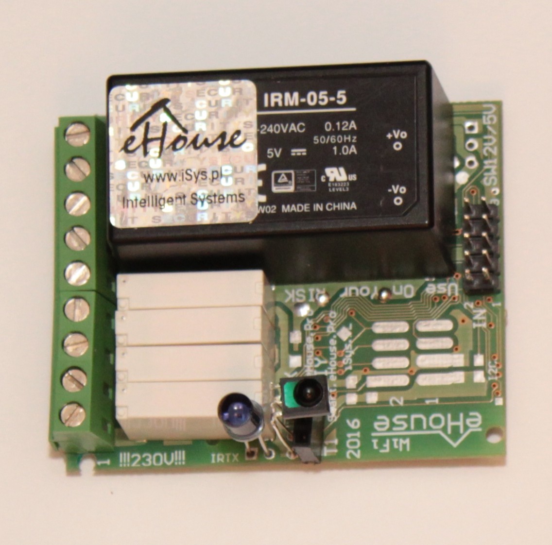
eHouse WiFi (wireless network) controllers are suitable for installation in old, finished building when wired systems are not taken into the account for installation. eHouse WiFi controllers can be placed near controlled devices or even put into Light covers due to very small dimensions
(61*52*27mm).
They can work directly in the same LAN/WiFi network infrastructure as eHouse LAN, PRO systems without any additional gateways, interfacing, for “plan B” or expansion eHouse wired installations into wireless part when it is more economic or only possibility.
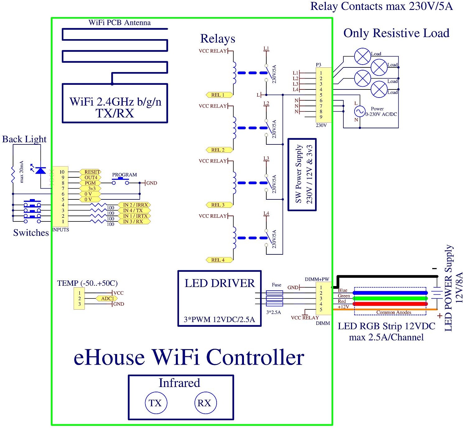
Connection Schematic:
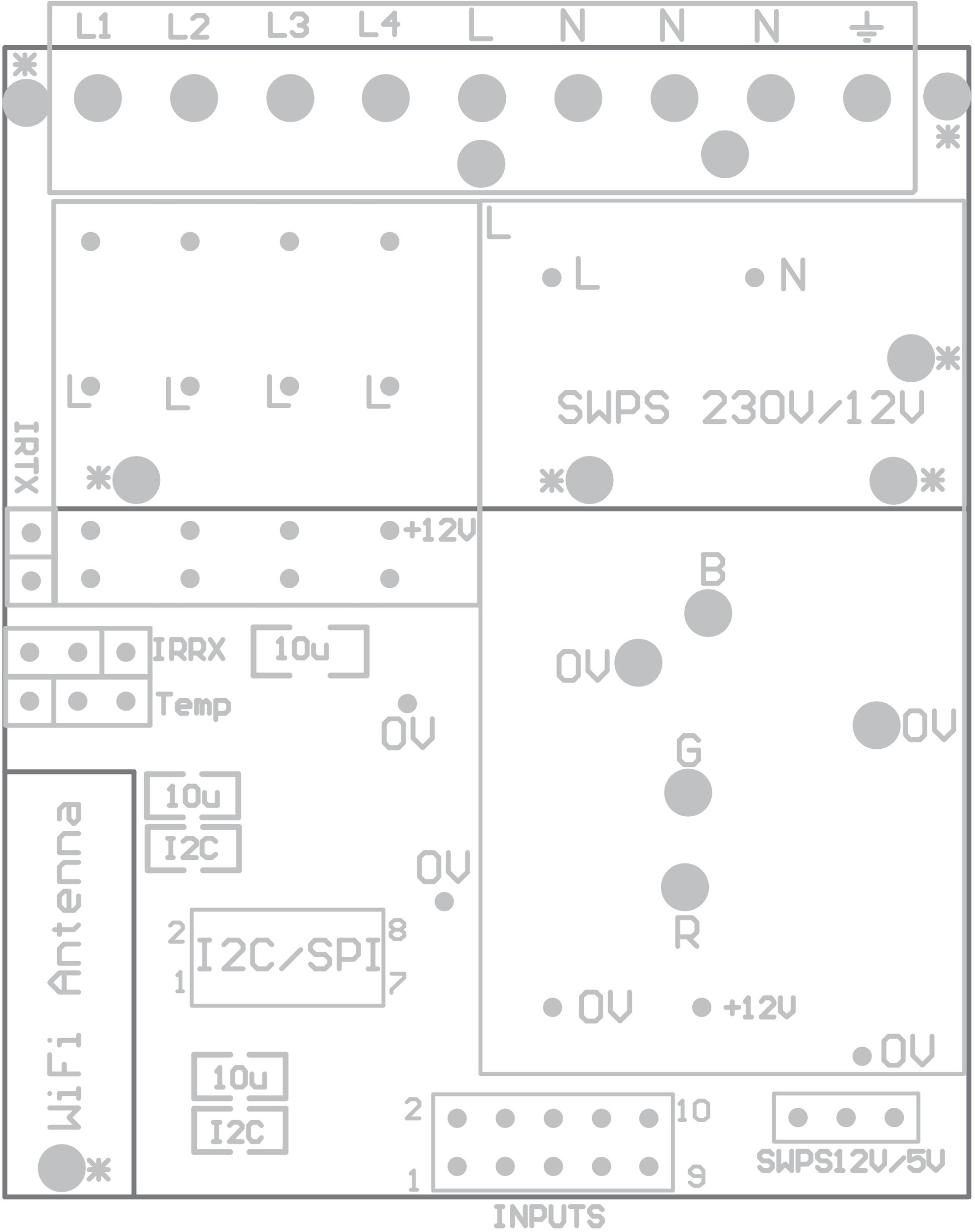
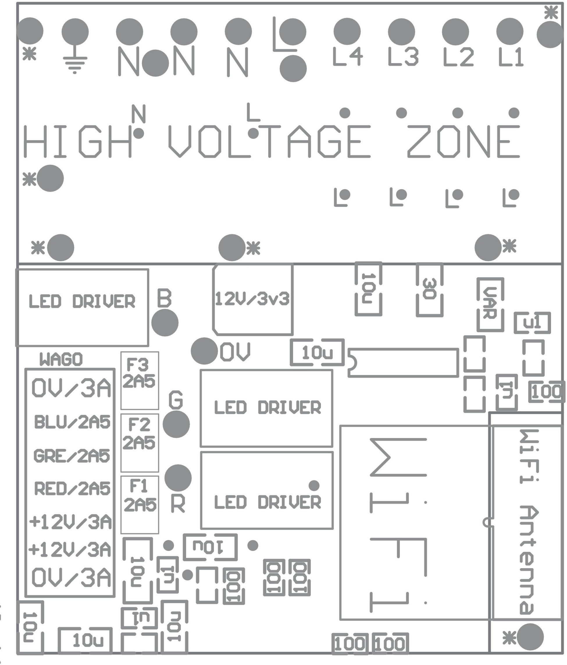
PCB components diagram:
Digital inputs (on/off) – socket IDC-10 pin male (INPUTS)
All digital inputs are connected through internal processor logic to 3v3 (Pull Up) and there are normally at high state (negative logic).
Switches or sensors connected between the input X and the ground (0V) of the system will activate input in this case.
All inputs are internally connected to other resources (IR, UART) which is mutually exclusive to use input and other functionality.
| No. | Name | Features mutually exclusive | Description |
| 1 | IN 3 | UART RX (Reception) | Input 3 (square soldering pad) |
| 2 | IN 1 | IR TX (infrared transmission) | Input 1 (positive logic – PULL down via IR TX) |
| 3 | IN 2 | IR RX (infrared reception) | Input 2 (not critical) |
| 4 | IN 4 | UART TX (transmission) | Input 4 |
| 5 | GND | – | 0V |
| 6 | GND | – | 0V |
| 7 | 3v3 | PS for electronic (Back-light LED max 20mA) | |
| 8 | PGM | Third party Firmware upgrade via UART | |
| 9 | OUT4 | DON’T Connect | |
| 10 | Reset | Restart of controller (shorten to 0V) |
Analog sensors – 3-pin SIP socket (TEMP x)
Analog input can measure voltage relative to the ground (0V) of eHouse controller.
Measurement range (0..1V) is available on this input. MCP9700 pining temperature sensors is compatible with this socket.
| No. | Pin. | TEMP x Description |
| 1 | VCC | (+3.3V regulated output from the controller) |
| 2 | AN x | analog input x |
| 3 | GND | 0V |
For the best result considering self-heating temperature sensor should be used with additional cables to maintain some distance from sensor to eHouse Controller.
PWM LED Dimmers +12VDC Power supply
All Dimmer outputs are Open Drain (OD) the maximum recommended output current is 2.5A (sinking to the GND – 0V). Do not connect external voltages only for connection LED stripes cathodes (-). Current larger than 2.5A may cause damage internal fuse, LED Power Driver or socket.
WAGO 6-7 pin socket (DIMM) Rev. A
| No. | SIGNAL | Description |
| 1 | GND | 0V/3A max – power supply for controller |
| 2 | DIMM1 | Dimmer 1 output max 12V/2.5A (RED) |
| 3 | DIMM2 | Dimmer 2 output max 12V/2.5A (GREEN) |
| 4 | DIMM3 | Dimmer 3 output max 12V/2.5A (BLUE) |
| 5 | VPOWER | +12V/3A max – power supply for controller (connect only when no 230V power supply is mounted on PCB) |
| 6 | VPOWER | +12V/3A max – power supply for controller (connect only when no 230V power supply is mounted on PCB) |
| 7 | GND | 0V/3A max – power supply for controller |
5 pin socket with screws (DIMM) Rev. B
| No. | SIGNAL | Description |
| 1 | GND | 0V/8A max – power supply for controller |
| 2 | DIMM1 | Dimmer 1 output 12V/2.5A (RED) |
| 3 | DIMM2 | Dimmer 2 output 12V/2.5A (GREEN) |
| 4 | DIMM3 | Dimmer 3 output 12V/2.5A (BLUE) |
| 5 | VPOWER | +12V/8A max – power supply for controller (connect only when no 230V power supply is mounted on PCB) |
Common anodes for dimmers are connected to +12V/8A power supply (directly) for RGB LED strip.
Relay contacts and 230V power supply – 9 pin screw socket (Relays)
| Pin No. | Signal | Description |
| 1 | Relay 1 contact | L1 (phase 1) |
| 2 | Relay 2 contact | L2 (phase 2) |
| 3 | Relay 3 contact | L3 (phase 3) |
| 4 | Relay 4 contact | L4 (phase 4) |
| 5 | Relay COM contacts | L (phase 230V – hot) – (when 230V power supply is mounted on PCB electronics is supplied from this voltage) |
| 6 | Neutral | N (230V neutral / cold) |
| 7 | Neutral | N (230V neutral / cold) |
| 8 | Neutral | N (230V neutral / cold) |
| 9 | SAFETY | Not Connected internally |