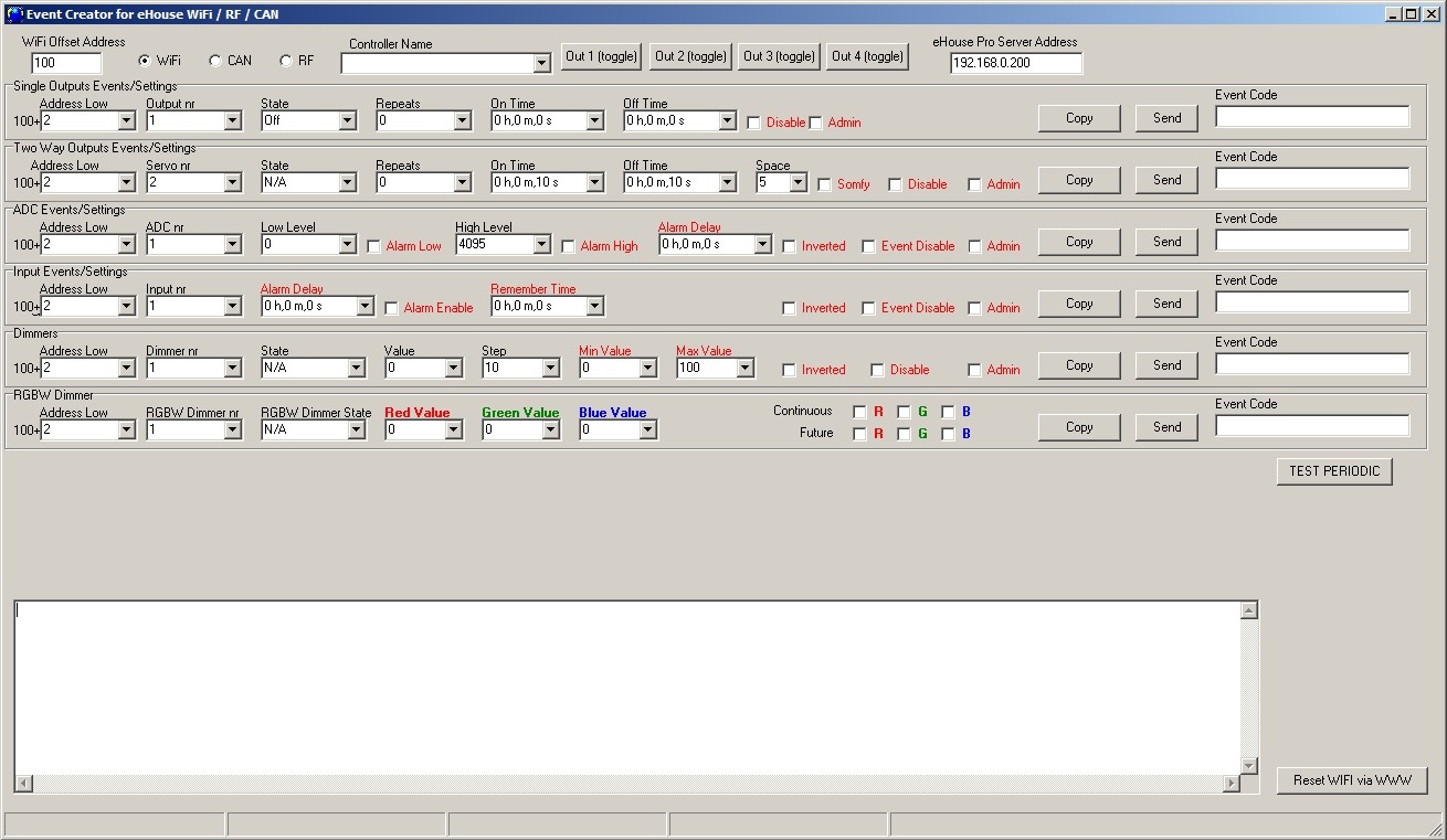
eHouse WiFi, CAN/RF home automation advanced event creation and ad-hoc configuration. eHouseWiFi.exe application has event editor for creating, running, copying advanced events for eHouse controllers.
For input/outputs eHouse WiFi & CAN/RF are the same
Advanced Event editor enables:
- create full spectrum of events for inputs, outpus, measurement inputs, dimmers for eHouse WiFi, CAN, RF controllers
- copy event for third party application usage
- send & execute events to the controller
- run ad-hoc configuration
- observe UDP logs
Changing the configuration (ad-hoc) of eHouse WiFi, CAN/RF intelligent controllers
Configuration of eHouse WiFi (CAN/RF too) smart home is carried out in the form of standard events eHouse and can be started at any time by sending an advanced events from event creator form (see picture below).
Changing configuration parameters (mark with red color) is possible only when the “admin” flag is on. In another case, part of the parameters may be ignored. Be particularly careful, if you change the settings of outputs connected to drives, solenoid valves, gates, etc. as incorrect configuration can cause damage of them.
Ad-Hoc configuration is especially valuable for initial testing of system with new actuators (checking drives ranges, timing, etc) before loading permanent configuration to controller for standard production work.
The configuration can be changed by re-sending the event changing the signal option again. Configuration also returns to the startup settings (default) after the reset controller.
Events for Inputs, Output, Drives, ADC, Dimmers are compatible for each WiFi, RF, CAN controllers. Controller type is chosen with Radio-button field “WiFi / CAN / RF”. In case of different controller address low should be changed.
For WiFi controllers (which are normally addressed not from 1) WiFi offset Address is specified for ease.
Event creator enables both copy event codes “Direct Event” for eHouse WiFi/CAN/RF controllers and send them to selected controller. eHouse WiFi events are sent with TCP/IP client directly to target controller via WiFi/LAN. eHouse CAN/RF events differs only with address and are sent via eHouse.PRO server which address is specified in “eHouse PRO Srv Address” field.
Text area shows UDP logs from controller for detecting problems or evaluating controller on first stage of work with them.
Analog measurement inputs (ADC)
eHouse WiFi Controller contains one analog input which has a measuring range <0..1V). Resolution of measurement is 10 bits (1024 levels). It gives about 1mV step for measurement. There are 2 thresholds (Low {Umin} and High {Umax}) for operations
Depending on the input voltage (Ux) there are 3 cases:
Ux < Umin when crossing threshold (downwards) the event is triggered, programmed in eHouseWiFi.exe application in "LOW Level Event" field
Umin = < Ux < = Umax when crossing one of thresholds (in direction Ux) the event is triggered, programmed in eHouseWiFi.exe application in "OK Event" field
Ux > Umax when crossing threshold (upwards) the event is triggered, programmed in eHouseWiFi.exe application in “HIGH Level Event” field
It should be noted that these are event codes “Direct Event” managed in Event Creator.
Another point is the thresholds of minimum (Umin) and maximum (Umax) measurement for inputs in the fields: “Low Level” and “High Level”. If you cross the value of these thresholds by the sensors will be running events associated with them respectively.
These inputs in relation to eHouse RS-485 or eHouse LAN controllers have a much more features and functionality.
Additional options for analog inputs:
- Invert (*) – the input is an negative scale mapping i.e. 100%-x
- Alarm Delay – delay issue alarm by the programmed time. This feature is very helpful for example when we measure a parameter, and run the event “to control” parameter. After the time of alarm delay if the value is not corrected (regulated) by the actuator the alarm is issued
- Alarm LOW – activating an alarm in the event of dropping measured value below the lower threshold. The alarm is activated with delay set in the “Alarm Delay” if the value is not corrected (regulated) before this time
- Alarm HIGH – activate the alarm in case of increase measured value above the upper threshold. The alarm is activated with delay set in the “Alarm Delay” if the value is not corrected (regulated) before this time
- Disable Event – blocking action thresholds related to events such as: if it is winter it is not necessary to control the solar collectors etc.
- Admin (*) – administrative settings. Some parameters can be changed only after setting “Admin” flag to protect against accidental erroneous controller configurations such as changing the flag “Invert”. Fields required Admin flag to be set are marked with red color in eHouseWiFi.exe application
(*) – Requires setting a flag Admin to modify this parameter.
Although eHouse WiFi controller contains only one real analog input, “eHouseWiFi.exe” application contains 4 ADC inputs to configure (future solutions and variants). It could be used for referencing analog sensors with digital serial interfaces like I2C, SPI, UART (for eHouse WiFi controllers / eHouse CAN/RF controllers has up to 4 ADC inputs).
Digital inputs (on/off)
Input has 2 logical states (inverted logic for safety – shortening to 0V for activation): low (0) left open and high when short to the 0V. With the change of state from low to high – controller run event programmed in the “Event” field for the appropriate input programmed in eHouseWiFi.exe application.
eHouse CAN/RF has 4 unallocated inputs on/off.
eHouse WiFi has 4 on/off inputs internally connected to some other controller resources (IR RX, IR TX, UART).
The Count of available inputs depends on hardware implementation, configuration and usage of other hardware resources (IR Transmitter {I1}/ IR Receiver{I2} , UART TX {I3}/ RX {I4}). Digital inputs (on/off) available for usage are internally connected to +3.3V by setting configuration of microprocessor inputs for inverted logic – activation by connecting to 0V (I2, I4). I1 input is internally connected to 0V by resistor of IR TX driver (has positive logic – should be connected to 3.3V for changing its state). I3 input depends on controller configuration.
Do not connect I1, I2 inputs if IR receiver or Transmitter is installed or output is configured for IR RX/TX.
To change normal input state (inverted) it should be shorted to ground (0V) through switches, sensors, etc.
There must be potential free contacts (without the applied external voltage), otherwise the voltage differences between grounds of the two systems or sensor damage, may result in exceeding the absolute maximum ratings of the system and damage the controller or make it unstable (eg. Reset without reason).
With the change of state from high to low to execute event programmed in “Direct Event” field for the appropriate input set in the web browser on the form of the controller configuration. This should be performed as discussed in the section on measurement inputs. Each input has an inertia about 0.5s to protect from responding to electromagnetic, electrostatic interference. It is therefore necessary to hold switch for more then 0.5s, to run programmed event. The same applies to the contact release: requires a pause between switching on and off about 0.5s, otherwise controllers treat the pulses as interference and ignore them. This protects output devices controlled by inputs from repeated turn on/off of the supply voltage (for example, children playing), thereby reducing the risk of damage to the device connected to the system.
Digital inputs are also much more functional in relation to eHouse RS-485 & LAN controllers inputs. In addition to the event assigned to run, a number of parameters associated with the inputs which are used for the advanced configuration:
- Inverted – negated input event is triggered when you release the switch, if you use contactors normally closed (eg. alarm detectors, reed confirming the closing of windows, doors, gates, etc.)
- Alarm Enable – when flag is set to raise an alarm associated with the input, the time set in the “Alarm Delay” if the input is still active after this time
- Alarm Delay – delay of the alarm for a programmed time. This parameter is especially valuable when you want to run the event, along with the inclusion of the switch or sensor which removing the cause of alarm during alarm delay time. An example might be a situation when we apply sensor for water level in the drainage wells to dry the building, associated with the event inclusion drain pump wells. In normal situations, when the pump will empty wells before the expiration of “Alarm Delay” time, the alarm will not be triggered. However, in case of failure, power failure or pump failure we will get an alarm
- Remember State – time of memorize the state of input, not to overlook the state change, as long as we are dealing with an important input or sensor
- Event Disable – Disable Event launch (if not necessary eg. season period)
- Admin – administration flag is necessary for changing serious input configuration parameters eg. inversion. Fields required setting admin flag are marked with red color on eHouseWiFi.exe application
Digital outputs with relays
eHouse WiFi controller has 4 digital output and up to 4 relays can be installed directly on its PCB.
Digital outputs turn on/off electrical equipment – by shorting (1 – closing) and open (0) relay contacts. It can be run as event automatically, manually from the control panel, assigned to the inputs (on/off), IR remote control, or as a consequence of the particular state of the system (eg low temperature, change input state, etc.). Digital outputs scheme is analogous to the eHouse RS-484 & LAN controllers, except that implementing relays are mounted on the controller board. Digital outputs are directly connected to relays 230V/5A. Relay contacts has all Common contacts shorten together for ease of connection.
Digital outputs have much more functionality than eHouse RS-485 or Ethernet controllers and have integrated functions available in all types of drivers (RoomManager, CommManager, HeatManager, ExternalManager).
Digital outputs switch on/off – can operate in the following modes:
single (individual) outputs (switching standard electrical devices on/off)
dual outputs (actuators control shutters, doors, awnings, windows, solenoids, actuators adjustable in both directions – open/close/stop)
quad outputs – all outputs working together, such as power control vents, heat recovery ventilators, fans, etc.
In addition, the settings are implemented functions:
- cyclic repetition of events
- count of repetitions
- on time
- off time
- control output in the operating mode (single, double, quadruple)
Modes are set independently for each output.
Single output mode:
- Disable (*) – blocking the output in single mode, if you use another operating mode for outputs. All events related to the individual output are ignored. Mostly for safety reasons (eg. when using in dual mode {drives control} – protection against accidental launch of event)
- Admin – Administrative flag unlocks advanced features for the security and safety configuration of external devices. Fields marked with red color on eHouseWiFi.exe application requires setting Admin flag
- State – The state of the output (Off/On/Toggle)
- Repeats – number of repetitions of the event beyond the initial start-up
- On Time – keeping output on for this time, after the expiration, the output will turn off automatically (if 0 output will be ON permanently)
- Off Time – output off time. This parameter is relevant if the “Repeats” is greater than 0, the output will be turned on again after the expiry of the above time
Dual outputs mode (one output direction Down (-), the other Up (+) – for safety we suggest to disable all outputs for single events):
- Disable (*) – blocking the outputs pairs working in dual mode, if you use another operating mode outputs. All events related to the dual outputs are ignored
- Admin – Administrative flag unlocks advanced features for security and safety configuration of external devices. Fields required setting of Admin flag are marked with red color in eHouseWiFi.exe application
- Somfy (*) – set “Somfy” drive standard mode
- State – The state of the output (N/A, Down, Up, Stop) for Somfy. (Stop, Down, Up, Stop) for all other drives
- On Time – Time on before stop the Up / Down outputs, after the expiration of the output will turn off automatically
- Off Time – time off for Up / Down outputs. If it is greater than 2 this time is treated as a “Disable Time” (Space) (Used for cyclic operations Repeats>0)
- Space (*) – the time for disabling outputs when changing movement direction of the drive. Protection against drive damage as a result of too rapid changes in direction or attempt to run simultaneously in both directions. The driver waits before turning on any output – this time causing delay in change of state. If the “Time Off” is greater than 2 – “Disable Time” is ignored
- Repeats – number of repetitions of the event beyond the initial start-up
(*) – Parameter change requires setting a flag “Admin”
PWM output (LED Dimmers)
PWM outputs are DC dimmers (Pulse Width Modulation), in which the duty ratio of square wave is controlled from 0..100%.
These outputs contains 12VDC/2.5A power drivers can smoothly adjust the LED or LED RGB lighting. It can be directly connected to LED/RGB stripes 12VDC (for multi color – Common Anode {+}). Up to 2.5A from each channel can be sink for LED Dimming. Bigger current than specified may cause permanent damage of internal fuse, led power driver, socket or even eHouse WiFi controller.
LED Stripe length should be limited so as not to exceed the current for one channel above 2.5A. Larger current may cause damage to the fuse which protects the controller or power supply.
Dimmers can work individually (3) or together as one RGBW (Red, Green , Blue) dimmer. Dimmers are much more functional than in eHouse RS-485, Ethernet controllers and compatible with CAN/RF controllers.
There are events and configuration control for individual dimmer and RGB dimmer together.
Individual dimmers have the following operating parameters:
- Value – the lighting level 0 .. 100 (scale is converted to human eye level thresholds)
- Min Value (*) – the minimum recommended lighting levels 0 – permanently OFF
- Max Value (*) – the maximum recommended level of illumination 100 – permanently ON
- State – Mode (N/A, Stop, +, -, Set)
- Step – change step for +, –
- Admin – administration flag to activate the advanced settings. Fields required setting Admin flag are marked with red color in “eHouseWiFi.exe” application
- Disable (*) – blocking dimmer. Events for the dimmer are ignored
- Inverted (*) – inverts output dimmer – the lighting level is inverted (100-x). This setting depends on the connected external driver or dimmer has an input inverting or not
(*) Change option requires setting “Admin” flag
Multiple dimmer (3 – RGB) working parameters:
- Settings Value Min, Value Max, Step, Invert, Disable, Value are taken from the individual settings of individual dimmers
- RGB Dimmer State – (N/A, Stop, +, -, Set) for all (unblocked channels) channel dimmers at once
- Values: Red, Green, Blue, White – target value for each dimmers respectively (White – only for eHouse CAN/RF controllers – event creator)
- Continuous dimmer /1 (Red) – the value of the light level changes between (min, max) with a programmed step for the dimmer – decorative lighting
- Continuous dimmer 2 (Green) – the value of the light level changes between (min, max) with a programmed step for the dimmer – decorative lighting
- Continuous dimmer 3 (Blue) – the value of the light level changes between (min, max) with a programmed step for the dimmer – decorative lighting
- Continuous dimmer 4 (White) – the value of the light level changes between (min, max) with a programmed step for the dimmer – decorative lighting (only for CAN/RF controllers – event creator)
Advanced event creator enables send each event to selected controller (pressing “Send” button for relevant I/O):
- directly for eHouse WiFi controller via TCP/IP client
- indirectly for eHouse CAN/RF via eHouse Pro server via TCP/IP client
Additionally it is possible to create an command (event code) for any controller and copy it to clipboard or edit field (by pressing “Copy” button for relevant I/O). It could be used for configuration, creating advanced event for third party applications or web control.