eHouse WiFi home automation system is configured the same way as eHouse LAN controller with eHouseWiFi.exe application (formerly CommManagerCfg.exe).
You should read posts:
smart home eHouse Wifi introduction
eHouse WiFi smart home connecting controllers
eHouse WiFi home automation basic configuration
eHouse WiFi intelligent home controller initialization
eHouseWiFi.exe – Configure Ethernet/WiFi controllers (formerly CommManagerCfg.exe)
eHouseWiFi.exe application is used to:
- perform complete configuration of eHouse LAN (eHouse4Ethernet) controllers
- perform complete configuration of eHouse WiFi controllers
- manually send events to eHouse Controllers (LAN, WiFi, CAN, RF)
- automatic sending event from the queue (PC Windows directory captured by auxiliary gateways)
- running transparent mode between Ethernet and serial interfaces to configure the extension modules and detect problems
- generate software configuration of all control panels, PADs, smartphones, Web Browser and any hardware platform
- checking logs for eHouse WiFi controllers (UDP logging)
For configuration of any Ethernet/WiFi Controller, Application must be run in following way “eHouseWiFi.exe / a:000201”, with the IP address of the controller parameter (6 characters – filled with zeros). In the absence of default parameter opens for CommManager configuration (address 000254).
Configuring CommManager, EthernetRoomManager with eHouseWiFi.exe application, was discussed in eHouse LAN documentation.
Current description is limited for eHouse WiFi configuration.
The application has a number of tabs that group the settings depending on type of Ethernet/WiFi Controller.
General Tab – General Settings.
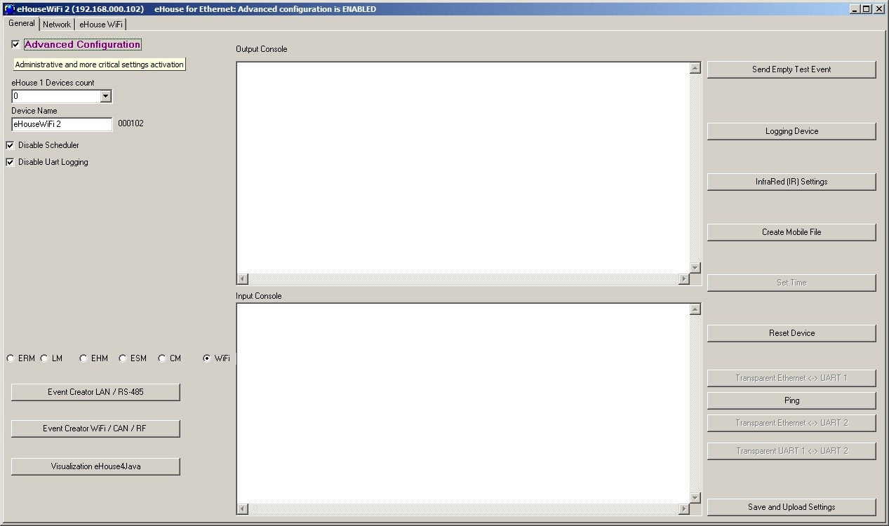
The General tab contains the following elements:
- Device Name – The name of the Ethernet/WiFi Controller
- Logging UART Disabled – Disables send logs via RS-232 (the flag must be checked for normal operation) (eHouse LAN only)
- WiFi – select the type of controller (radio button) – eHouse WiFi (other types explained in eHouse LAN documentation)
- Infrared Settings – Infrared Transmission/Reception Settings for eHouse WiFi
- Reset Device – Force reset controller
- Save and Update Settings – write configuration, settings and upload to the controller.
- Event Creator – Edit and run system events
- Event Creator WiFi/CAN/RF – creating advanced events for eHouse WiFi, CAN, RF controllers
- Advanced Configuration – Enables more advanced features
- The first message window is used to display text logs
- The second text box is used for transparent mode putting text to be sent to the controller. Pressing “Enter” Sends data to the controller. For ASCII text only
- Ping – check ping to current device
Description/text of button may change during software update or language versions.
Language versions can be edit in “%eHouse%/lang/” directory for each windows code page and application revision individually.
Network Settings
In the “Net Settings” you can also define a controller configuration valid options. For new controller default setting is copied from ConfigAux.exe application for all controllers in the installation.
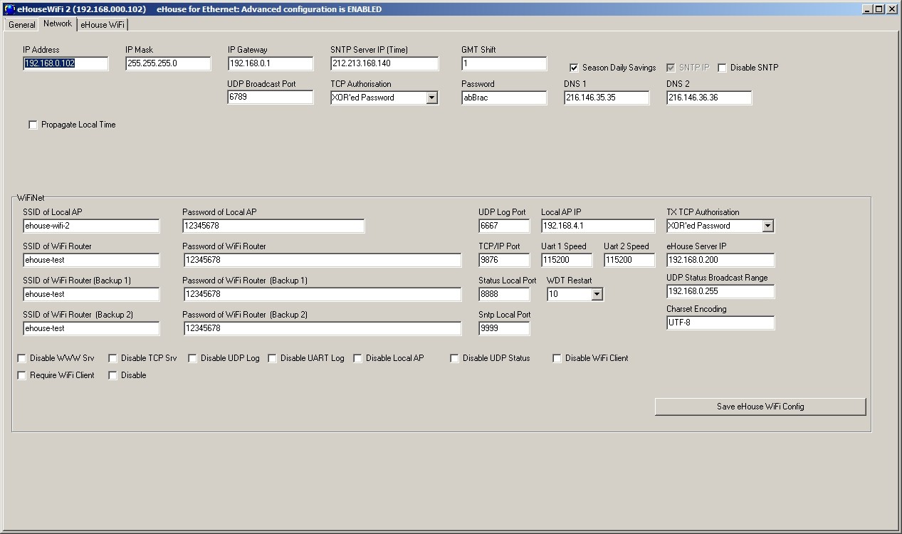
- IP Address – (not recommended to change after initial initialization of controller – it must be the same as the address of the controller configuration) must be in network address 192.168.x.x
- IP Mask (not recommended to change should be as low as possible: 255.255.255.0)
- IP Gateway (gateway for Internet access)
- SNTP Server IP – IP address of the time server SNTP services
- GMT Shift – Time Offset from GMT / time zone
- Season Daily Savings – Activate seasonal time changes
- SNTP IP – Use IP of SNTP server address instead of the DNS name. For best results use local (inside LAN) SNTP server.
- MAC Address – Do not change (Mac address is assigned automatically – the last byte taken from the youngest byte of IP address)
- Host Name – not used
- Broadcast UDP Port – Port for distribute data from the controller status via UDP (0 blocks UDP Broadcasting)
- TCP Authorization – Minimal Method of Authorization to the TCP/IP server of controllers (for further entries from the list imply earlier, safer ways). Used for third party applications including eHouse4Java, eHouseAndroid, eHouse4WindowsMobile
- DNS 1, DNS 2 – DNS server addresses
eHouse WiFi Controllers settings (taken automatically from ConfigAux.exe application for new controller):
- Local AP SSID – Local Access Point SSID name (up to 30 chars)
- Password for Local SSID – Password for local Access Point (up to 60 chars)
- SSID for WiFi Infrastructure X – up to 3 WiFi infrastructures to connect (for backup and redundancy)
- Password for WiFi Infrastructure X – passwords for each WiFi network Infrastructures
- TX Authorization – Authorization type for sending commands to other controllers (use Challange-response).
- UDP LOG Port – Wireless logging of controller to UDP port
- TCP/IP Port – eHouse TCP/IP Server port for command reception (all eHouse LAN, WiFi must have the same port set)
- UDP Broadcast Port – for sending statuses via UDP (all eHouse LAN, WiFi, Pro should have the same port set unless we not want filter statuses in eHouse panels software)
- eHouse Server IP – Linux Server IP hosting: eHouse Pro, eHouse4cServer application for sending events to other eHouse System variants (RF/CAN, RS-485, etc.)
- MAC Address – WiFi network adapter MAC adres hex coded (2 LSB automatically set for each controller depending on IP address)
- xxx Local Port – local ports of servers – don’t change if there is no problem
- Password for LAN and WiFi controllers – common eHouse LAN, WiFi, PRO password for XOR password or Password Authorization types.
- UART 1,2 Speed – speed for available UARTs (default 115200)
- UDP Status Broadcast Range – broadcasting range for UDP status
- Charset Encoding – for internal WWW Server (default UTF-8)
- Disable WWW Server – Disable local WWW (REST) (increase efficiency and security)
- Disable TCP Server – Disable local eHouse TCP/IP server (don’t change)
- Disable UDP Log – disable sending wireless logs via UDP protocol from eHouse WiFi (increase efficiency)
- Disable UART Log – disable sending Logs to serial port from eHouse WiFi (increase efficiency)
- Disable local AP – disable local Access Point (increase efficiency and security)
- Disable UDP Status – disable UDP status for eHouse system (only for usage outside eHouse home automation system infrastructure)
- Disable WiFi Client – disable WiFi Station ode (only local Access Point mode – outside eHouse)
- Require WiFi Client – requires WiFi Router (infrastructure) for connection
eHouse WiFi controller is much smaller than ERM and all initial settings are located on single form
“eHouse WiFi” (picture below).
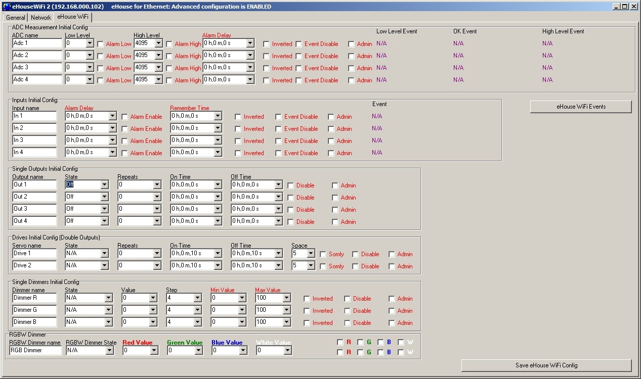
eHouse WiFi Inputs, outputs, signal settings
All signals (Single outputs, double output, dimmers, RGB dimmer, inputs, ADC input) and their options were explained earlier.
To Change main settings, it is necessary to check activation flag “Advanced Configuration” from “General” Form.
Each signal has some individual parameters. Initial configuration for each I/O is set by running proper event, combined from all of these parameters. Running event (changing ad-hoc configuration) is also possible the same way as running initial settings (start condition) on restart controller. Some of parameters require setting of Admin flag. Parameters requiring Admin flag are marked with red color.
eHouseWiFi.exe application enables naming each input/output individually for each controller.
Edition of each name can be performed in edit fields. After setting all names “Save WiFi Config” button should be pressed.
Analog measurement inputs
eHouse WiFi has only one true analog (0..1v) input for measurement (voltage, temperature, etc). In most cases MCP9700 is installed or socket to connect it outside the cover for better measurement results of free air. Other analog inputs are virtual for future usage in case of connection measurement sensors with digital interfaces (SPI, I2C, UART)
number of available measuring inputs depends on the type of controller, hardware version,
connected to the internal sensors and the controller firmware. It may therefore happen that a part of the input is occupied and can not be used. For busy inputs must not be connected in parallel or shorted sensors as this may skew the measurements or damage the controller
events can be assigned to the upper and lower thresholds of the relevant system events, eg. (adjustment of physical value or signaling the exceeded limit). This is done by clicking on the label “Low Level Event” – wizard, selecting from a list of events and the corresponding event by clicking “Accept”
the upper threshold is set by clicking “High Level Event” label, by selecting desired event and clicking “Accept”
valid range event is set by clicking “OK Event” label, by selecting desired event and clicking “Accept”
after these steps, it is necessary to press the “Save eHouse WiFi Config” and on “General” Form “Save and upload settings” close / reopen application is required to update names, events, choice list values
when you enter a value of thresholds in selectable data field, be sure to press the down arrow to select the closest value from the list.
eHouse WiFi Controller contains one analog input which has a measuring range <0..1V). Resolution of measurement is 10 bits (1024 levels). It gives about 1mV step for measurement. There are 2 thresholds (Low {Umin} and High {Umax}) for operations Depending on the input voltage (Ux) there are 3 cases: Ux < Umin when crossing threshold (downwards) the event is triggered, programmed in eHouseWiFi.exe application in “LOW Level Event” field Umin = < Ux < = Umax when crossing one of thresholds (in direction Ux) the event is triggered, programmed in eHouseWiFi.exe application in “OK Event” field Ux > Umax when crossing threshold (upwards) the event is triggered, programmed in eHouseWiFi.exe application in “HIGH Level Event” field
It should be noted that these are event codes “Direct Event” managed in Event Creator.
Another point is the thresholds of minimum (Umin) and maximum (Umax) measurement for inputs in the fields: “Low Level” and “High Level”. If you cross the value of these thresholds by the sensors will be running events associated with them respectively.
These inputs in relation to eHouse RS-485 or eHouse LAN controllers have a much more features and functionality and the same as eHouse CAN/RF controllers.
Additional options for analog inputs:
- Invert (*) – the input is an negative scale mapping i.e. 100%-x
- Alarm Delay – delay issue alarm by the programmed time. This feature is very helpful for example when we measure a parameter, and run the event “to control” parameter. After the time of alarm delay if the value is not corrected (regulated) by the actuator the alarm is issued
- Alarm LOW – activating an alarm in the event of dropping measured value below the lower threshold. The alarm is activated with delay set in the “Alarm Delay” if the value is not corrected (regulated) before this time
- Alarm HIGH – activate the alarm in case of increase measured value above the upper threshold. The alarm is activated with delay set in the “Alarm Delay” if the value is not corrected (regulated) before this time
- Disable Event – blocking action thresholds related to events such as: if it is winter it is not necessary to control the solar collectors etc.
- Admin (*) – administrative settings. Some parameters can be changed only after setting “Admin” flag to protect against accidental erroneous controller configurations such as changing the flag “Invert”. Fields required Admin flag to be set are marked with red color in eHouseWiFi.exe application
(*) – Requires setting a flag Admin to modify this parameter.
Although eHouse WiFi controller contains only one real analog input, “eHouseWiFi.exe” application contains 4 ADC inputs to configure (future solutions and variants). It could be used for referencing analog sensors with digital serial interfaces like I2C, SPI, UART.
Digital Input Settings
Input count (0..4) depends of other resources used or implemented in the eHouse WiFi Controllers (eg. enabling UART takes 2 digital inputs: I3, I4,
IR Receiver takes: I1,
IR transmitter takes: I2.
Please refer to following table for more information:
| Function | Utilization | Description | Trigger | Conditions | |
| IR RX | I1 | Inverted (pull up) | 0V | installed IR Receiver | |
| IR TX | I2 | Non Inverted (pull down) | 3,3V | don’t use enabled IR | Transmitter |
| UART TX | I3 | Inverted (pull up) | 0V | enable UART or UART Logging | |
| UART RX | I4 | Non Inverted (pull down) | 3,3V | enable UART |
Shorten input to 0V or 3v3 may damage it, if allocated internally for alternate functions.
UART pins are not internally connected with additional hardware so usage as inputs only depend on configuration not installed hardware.
Configuration of inputs:
- the names of digital inputs can be enter or change after activation of “Advanced Configuration” option on General Form. For WiFi Controller it is available in “eHouse WiFi” Tabs
- the names shall be entered in editable field for input and put new short, descriptive and unique value
- set Invert Flag regarding to table above and sensor type (normal / invert), changing the flag Invert
- in the case of inverted (pull up) inputs controller react for short input to ground. Non inverted (pull down) input are trigger on connecting input for microprocessor power supply (3.3V)
- then you can assign any event of eHouse system to each input (pressing Event label)
- this is done by clicking on the labels marked as ‘N/A’ (not programmed for input), and select from the list of events on corresponding wizard, and press the “Accept” (picture below)
- When all changes are made press “Save WiFi Config” button and “Save and update Settings” on “General” form , to save the configuration and upload it to controller.
The number of available inputs depend on the type of controller, hardware version, firmware, etc. User has to realize how many inputs are available for current type of controller and do not try to program or connect more than the available quantity as it can lead to resource conflicts with other inputs, on-board sensors, communication interfaces or resources, damage inputs or whole controller.
There must be potential free contacts (without the applied external voltage), otherwise the voltage differences between grounds of the two systems or sensor damage, may result in exceeding the absolute maximum ratings of the system and damage the controller or make it unstable (eg. Reset without reason).
With the change of state from high to low to execute event programmed in “Direct Event” field for the appropriate input set in the web browser on the form of the controller configuration. This should be performed as discussed in the section on measurement inputs. Each input has an inertia about 0.5s to protect from responding to electromagnetic, electrostatic interference. It is therefore necessary to hold switch for more then 0.5s, to run programmed event. The same applies to the contact release: requires a pause between switching on and off about 0.5s, otherwise controllers treat the pulses as interference and ignore them. This protects output devices controlled by inputs from repeated turn on/off of the supply voltage (for example, children playing), thereby reducing the risk of damage to the device connected to the system.
Digital inputs are also much more functional in relation to eHouse RS-485 & LAN controllers inputs (it has the same functionality as eHouse CAN/RF controllers). In addition to the event assigned to run, a number of parameters associated with the inputs which are used for the advanced configuration:
- Inverted – negated input event is triggered when you release the switch, if you use contactors normally closed (eg. alarm detectors, reed confirming the closing of windows, doors, gates, etc.)
- Alarm Enable – when flag is set to raise an alarm associated with the input, the time set in the “Alarm Delay” if the input is still active after this time
- Alarm Delay – delay of the alarm for a programmed time. This parameter is especially valuable when you want to run the event, along with the inclusion of the switch or sensor which removing the cause of alarm during alarm delay time. An example might be a situation when we apply sensor for water level in the drainage wells to dry the building, associated with the event inclusion drain pump wells. In normal situations, when the pump will empty wells before the expiration of “Alarm Delay” time, the alarm will not be triggered. However, in case of failure, power failure or pump failure we will get an alarm
- Remember State – time of memorize the state of input, not to overlook the state change, as long as we are dealing with an important input or sensor
- Event Disable – Disable Event launch (if not necessary eg. season period)
- Admin – administration flag is necessary for changing serious input configuration parameters eg. inversion. Fields required setting admin flag are marked with red color on eHouseWiFi.exe application
Digital outputs with relays
eHouse WiFi controller has 4 digital output and up to 4 relays can be installed directly on its PCB.
Digital outputs turn on/off electrical equipment – by shorting (1 – closing) and open (0) relay contacts. It can be run as event automatically, manually from the control panel, assigned to the inputs (on/off), IR remote control, or as a consequence of the particular state of the system (eg low temperature, change input state, etc.). Digital outputs scheme is analogous to the eHouse RS-484 & LAN controllers, except that implementing relays are mounted on the controller board. Digital outputs are directly connected to relays 230V/5A. Relay contacts has all Common contacts shorten together for ease of connection.
Digital outputs have much more functionality than eHouse RS-485 or Ethernet controllers and have integrated functions available in all types of drivers (RoomManager, CommManager, HeatManager, ExternalManager) and are compatible with (eHouse CAN/RF controller).
Digital outputs switch on/off – can operate in the following modes:
- single (individual) outputs (switching standard electrical devices on/off)
- dual outputs (actuators control shutters, doors, awnings, windows, solenoids, actuators adjustable in both directions – open/close/stop)
- quad outputs – all outputs working together, such as power control vents, heat recovery ventilators, fans, etc.
In addition, the settings are implemented functions:
- cyclic repetition of events
- count of repetitions
- on time
- off time
control output in the operating mode (single, double, quadruple)
Modes are set independently for each output.
Single output mode:
- Disable (*) – blocking the output in single mode, if you use another operating mode for outputs. All events related to the individual output are ignored. Mostly for safety reasons (eg. when using in dual mode {drives control} – protection against accidental launch of event)
- Admin – Administrative flag unlocks advanced features for the security and safety configuration of external devices. Fields marked with red color on eHouseWiFi.exe application requires setting Admin flag
- State – The state of the output (Off/On/Toggle)
- Repeats – number of repetitions of the event beyond the initial start-up
- On Time – keeping output on for this time, after the expiration, the output will turn off automatically (if 0 output will be ON permanently)
- Off Time – output off time. This parameter is relevant if the “Repeats” is greater than 0, the output will be turned on again after the expiry of the above time
Dual outputs mode (one output direction Down (-), the other Up (+) – for safety we suggest to disable all outputs for single events):
- Disable (*) – blocking the outputs pairs working in dual mode, if you use another operating mode outputs. All events related to the dual outputs are ignored
- Admin – Administrative flag unlocks advanced features for security and safety configuration of external devices. Fields required setting of Admin flag are marked with red color in eHouseWiFi.exe application
- Somfy (*) – set “Somfy” drive standard mode
- State – The state of the output (N/A, Down, Up, Stop) for Somfy. (Stop, Down, Up, Stop) for all other drives
- On Time – Time on before stop the Up / Down outputs, after the expiration of the output will turn off automatically
- Off Time – time off for Up / Down outputs. If it is greater than 2 this time is treated as a “Disable Time” (Space) (Used for cyclic operations Repeats>0)
- Space (*) – the time for disabling outputs when changing movement direction of the drive. Protection against drive damage as a result of too rapid changes in direction or attempt to run simultaneously in both directions. The driver waits before turning on any output – this time causing delay in change of state. If the “Time Off” is greater than 2 – “Disable Time” is ignored
- Repeats – number of repetitions of the event beyond the initial start-up
(*) – Parameter change requires setting a flag “Admin”
PWM output (LED Dimmers)
PWM outputs are DC dimmers (Pulse Width Modulation), in which the duty ratio of square wave is controlled from 0..100%.
These outputs contains 12VDC/2.5A power drivers can smoothly adjust the LED or LED RGB lighting. It can be directly connected to LED/RGB stripes 12VDC (for multi color – Common Anode {+}). Up to 2.5A from each channel can be sink for LED Dimming. Bigger current than specified may cause permanent damage of internal fuse, led power driver, socket or even eHouse WiFi controller.
LED Stripe length should be limited so as not to exceed the current for one channel above 2.5A. Larger current may cause damage to the fuse which protects the controller or power supply.
Dimmers can work individually (3) or together as one RGBW (Red, Green , Blue) dimmer. Dimmers are much more functional than in eHouse RS-485, Ethernet controllers and compatible with CAN/RF controllers.
There are events and configuration control for individual dimmer and RGB dimmer together.
Individual dimmers have the following operating parameters:
- Value – the lighting level 0 .. 100 (scale is converted to human eye level thresholds)
- Min Value (*) – the minimum recommended lighting levels 0 – permanently OFF
- Max Value (*) – the maximum recommended level of illumination 100 – permanently ON
- State – Mode (N/A, Stop, +, -, Set)
- Step – change step for +, –
- Admin – administration flag to activate the advanced settings. Fields required setting Admin flag are marked with red color in “eHouseWiFi.exe” application
- Disable (*) – blocking dimmer. Events for the dimmer are ignored
- Inverted (*) – inverts output dimmer – the lighting level is inverted (100-x). This setting depends on the connected external driver or dimmer has an input inverting or not
(*) Change option requires setting “Admin” flag
Multiple dimmer (3 – RGB) working parameters:
- Settings Value Min, Value Max, Step, Invert, Disable, Value are taken from the individual settings of individual dimmers
- RGB Dimmer State – (N/A, Stop, +, -, Set) for all (unblocked channels) channel dimmers at once
- Values: Red, Green, Blue, White – target value for each dimmers respectively (White – only for eHouse CAN/RF controllers – event creator)
- Continuous dimmer 1 (Red) – the value of the light level changes between (min, max) with a programmed step for the dimmer – decorative lighting
- Continuous dimmer 2 (Green) – the value of the light level changes between (min, max) with a programmed step for the dimmer – decorative lighting
- Continuous dimmer 3 (Blue) – the value of the light level changes between (min, max) with a programmed step for the dimmer – decorative lighting
- Continuous dimmer 4 (White) – the value of the light level changes between (min, max) with a programmed step for the dimmer – decorative lighting (only for CAN/RF controllers – event creator)
After setting all inputs/outputs and network configuration user should press “Save eHouse WiFi Config” and on general form “Save and Upload settings”.