eHouse LAN RoomManager – Building Automation, connection at the building.
Installation of a mini-switchboard and midi-switchboard in a residential building.
We can install the small room switchboard in place, that will eventually be covered with light furniture.
The point is to allow easy access to the switchgear, if service is needed, and to avoid marring the room where it is installed.
The switchgear can also be installed in adjacent rooms (eg utility rooms), which require increase in cable length.
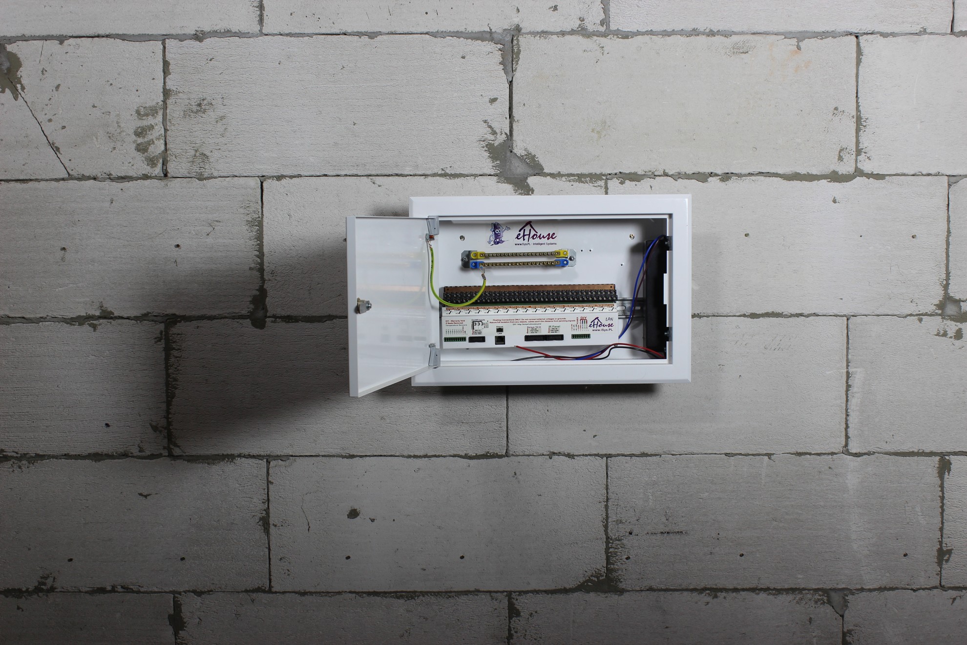
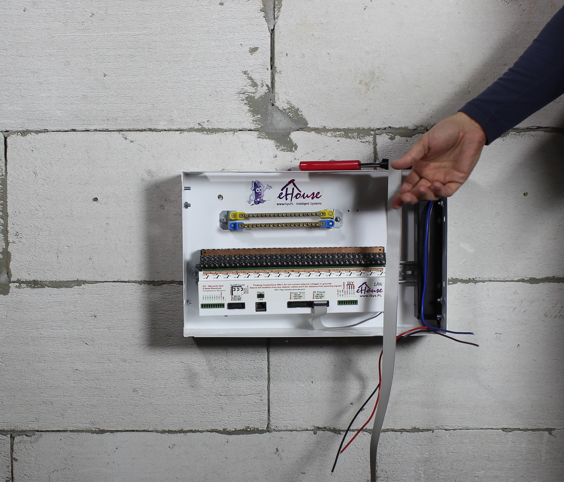
Installation of the switchgear on the wall:
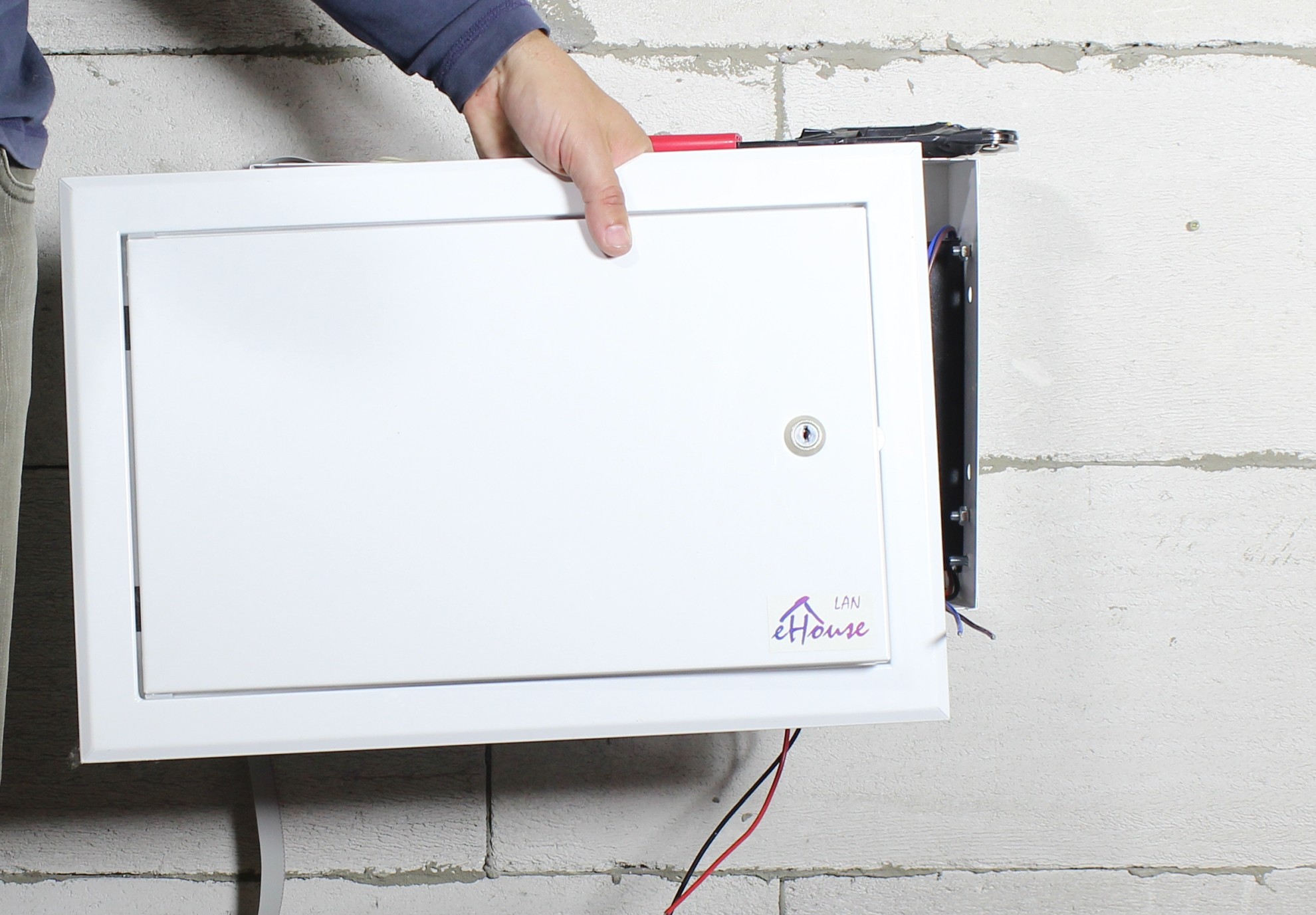
The switchgears are concealed with detachable frames so we can remove them until finishing the walls (including final painting).
This article is instructional and boxes and cans are screwed directly to the wall, without drilling wholes for it.
In the normal case, wholes should be cut under the switchboard and cans to determine the proper depth of foundation of these elements.
Flat strips (for low voltage inputs) do not require forging furrows because they are about 2mm thick.
We fix the switchboard on the wall preferably at the height of electrical sockets (it has several mounting holes in the side and back of wall ).
We dismantle the frame so as not to damage or scratch it.
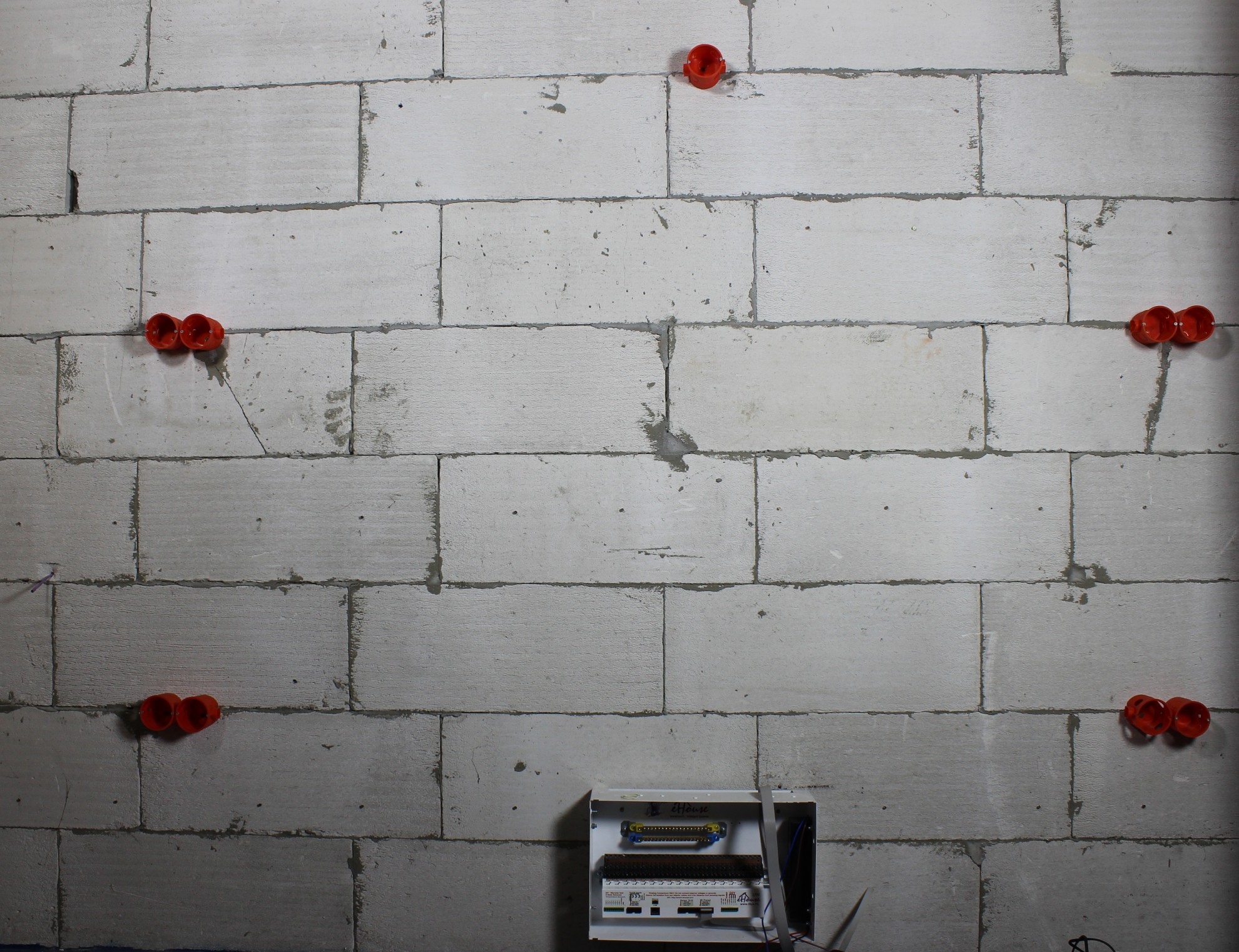
We mount electrical cans in the wall (preferably 6cm deep).
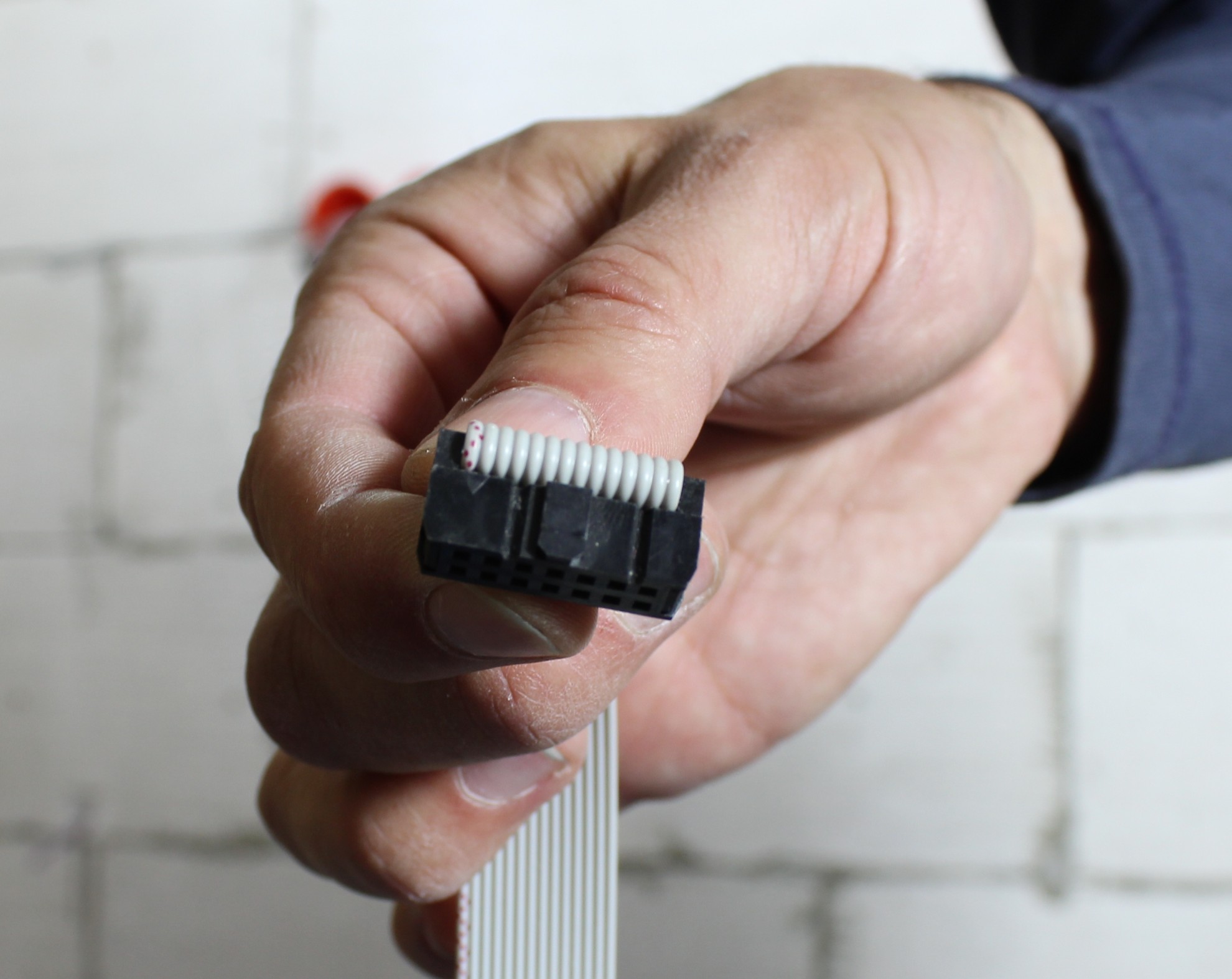
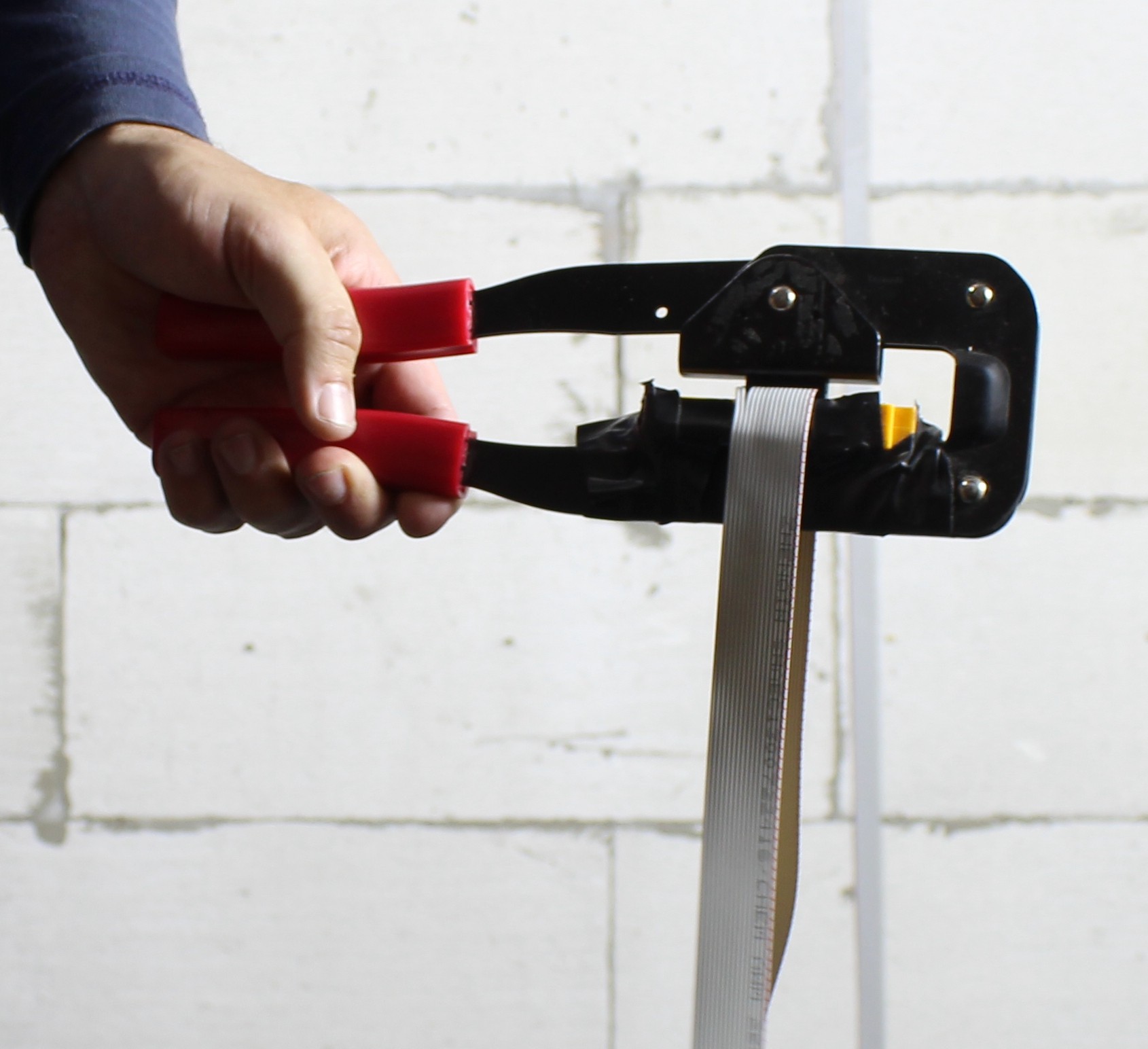
If we do not have prepared IDC-16/14 wires for the infra-red panel / switches, we clip them. It is necessary to clamp at right angles and make sure that the tape does not move when clamping.
The plastic insert of the crimper should be glued with insulating tape so that it does not move.
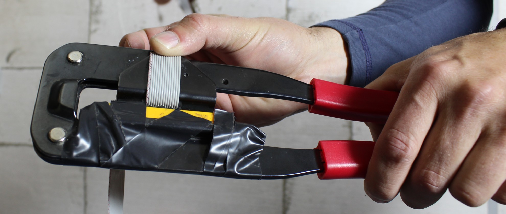
The connector is marked with an arrow next to pin no. 1, while the flat cable with red color is marked with cable no. 1 (should be adapted with each other).
We connect the flat cable of the infrared panel to the appropriate “IR Panel” connector to measure the length of the wire we need. The tape should be kept at a minimum distance of 20cm from 230V interfering wires and communication interfaces (eg Ethernet).
The infrared panel contains: temperature sensor, lighting sensor, infrared transmitter and infrared receiver.
To perform all its functions correctly:
- must be installed in front of A/V equipment which it intends to control at a distance of less than 8mb and must “see” this device.
- if we intend to correctly measure the temperature, it should be as exposed as possible in a place, where there is good air exchange (at a height of 1.5 m from the floor)
- the length of the flat cable must be less than 8m
- ensure the distance of this tape over the entire length of 20cm from other wires
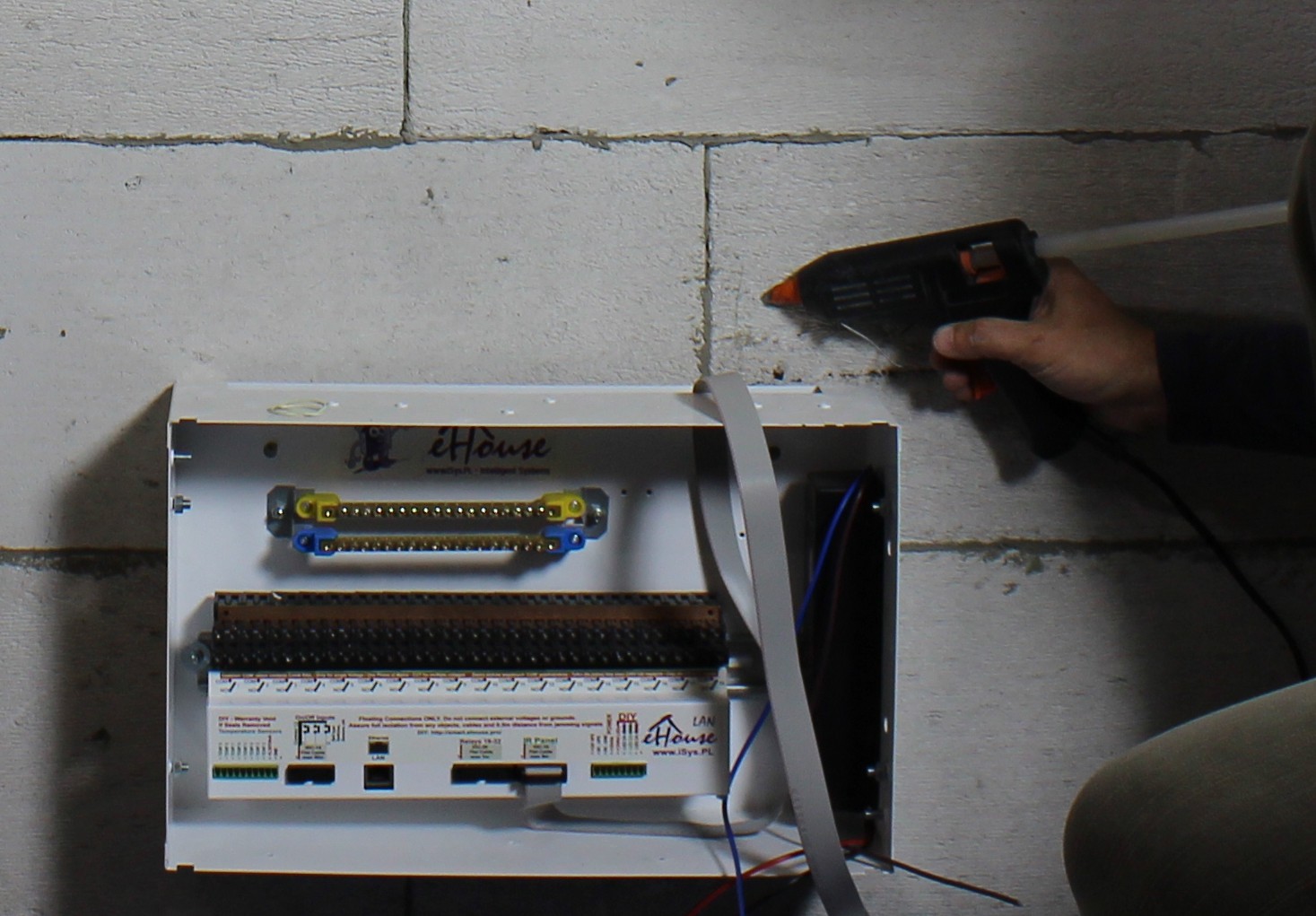
We spread the flat tape only vertically and horizontally (no slants), gluing it, eg with a glue gun, to withstand the plastering process or gluing G-K boards.
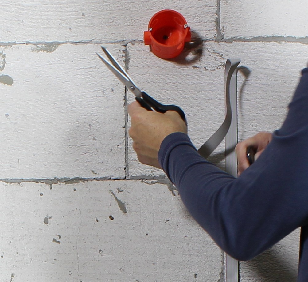
Cutting the cable with sharp scissors with reserve of 20-50cm. If you intend to place the panel outside the electrical box, you can increase this length.

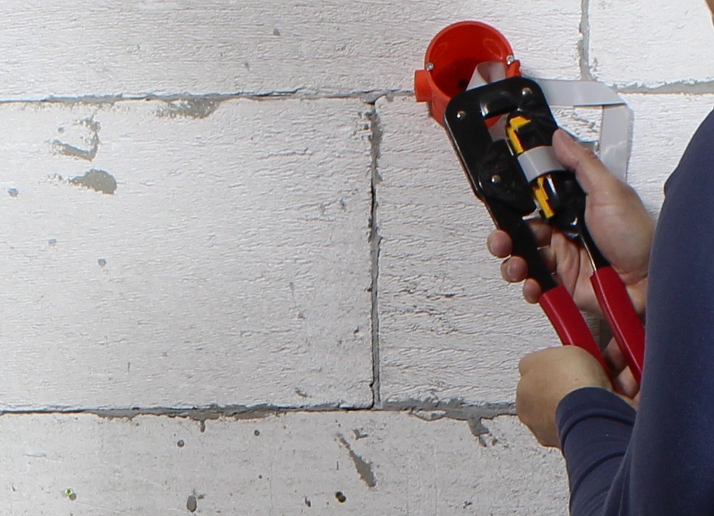
We tighten the IDC-16 quick connector for the infrared panel.
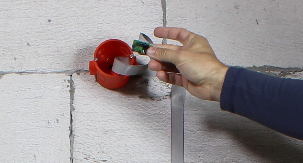
We install an infrared panel for testing instalation before plastering the building.
We clamp the IDC-14 quick connector for on/off inputs (switches). In the controller it is necessary to tighten the 14-pin IDC connector. You can do it on the IDC-16 flat cable by pulling the last 2 wires. However, they may be useful in the future, for example, to connect the illumination of sockets or in situations when a cable breaks during construction works.
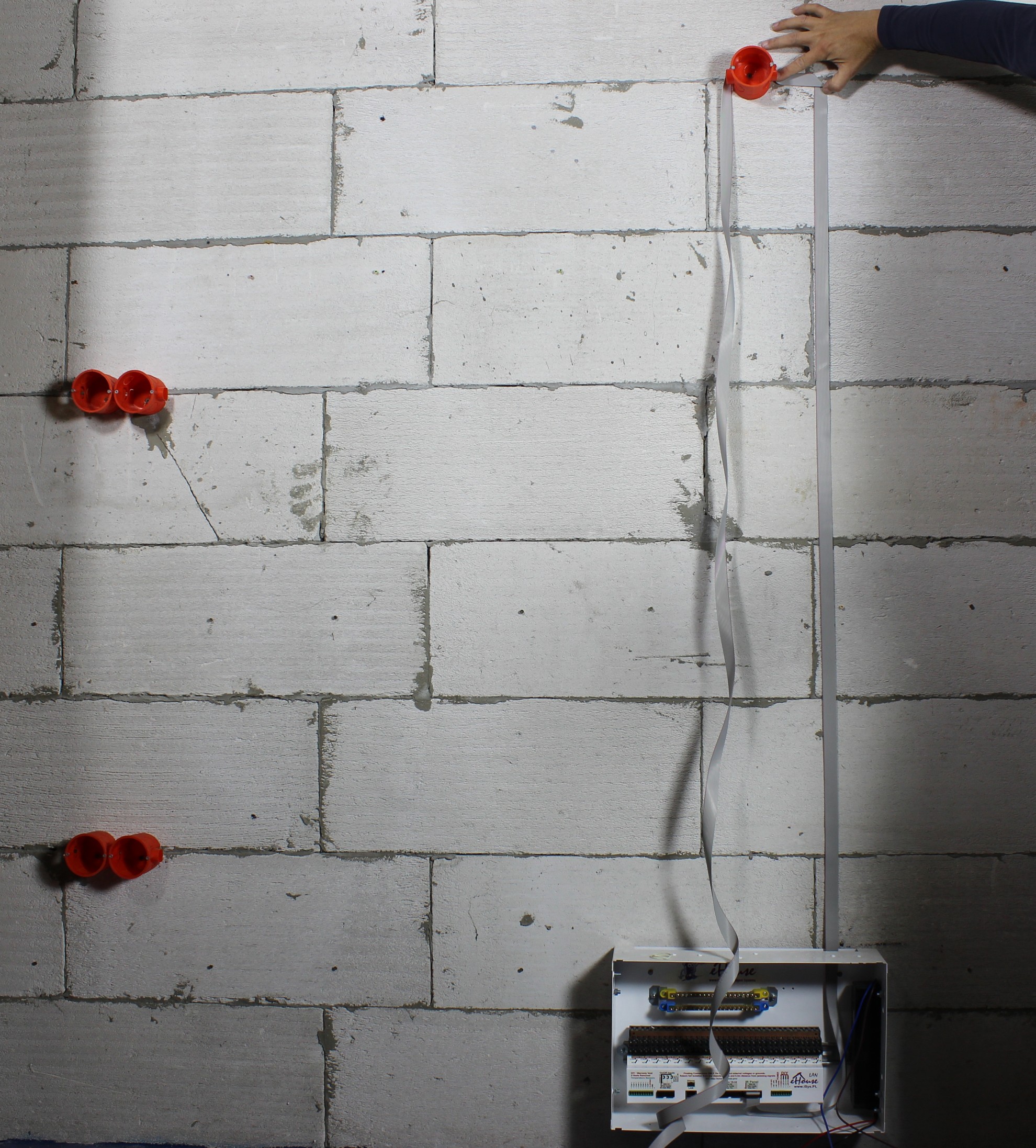
Connecting switches cable (digital inputs) to the switchgear:


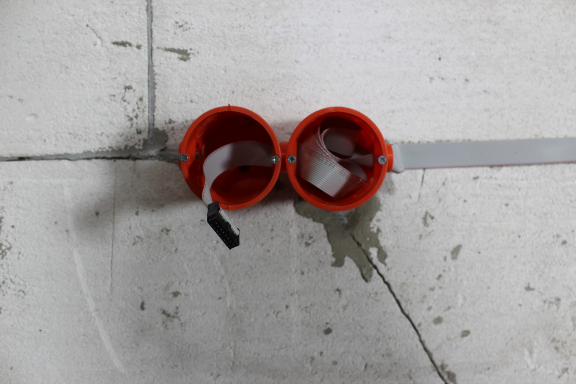
Making a loop in cans at least 5cm above the top of the box so that you can tighten IDC-14/IDC-16 quick connectors.

The tape is further fed in series to subsequent cans of switches. It is possible to duplicate the switches in various places of the room.

The tape going the other way from the mini switchboard.
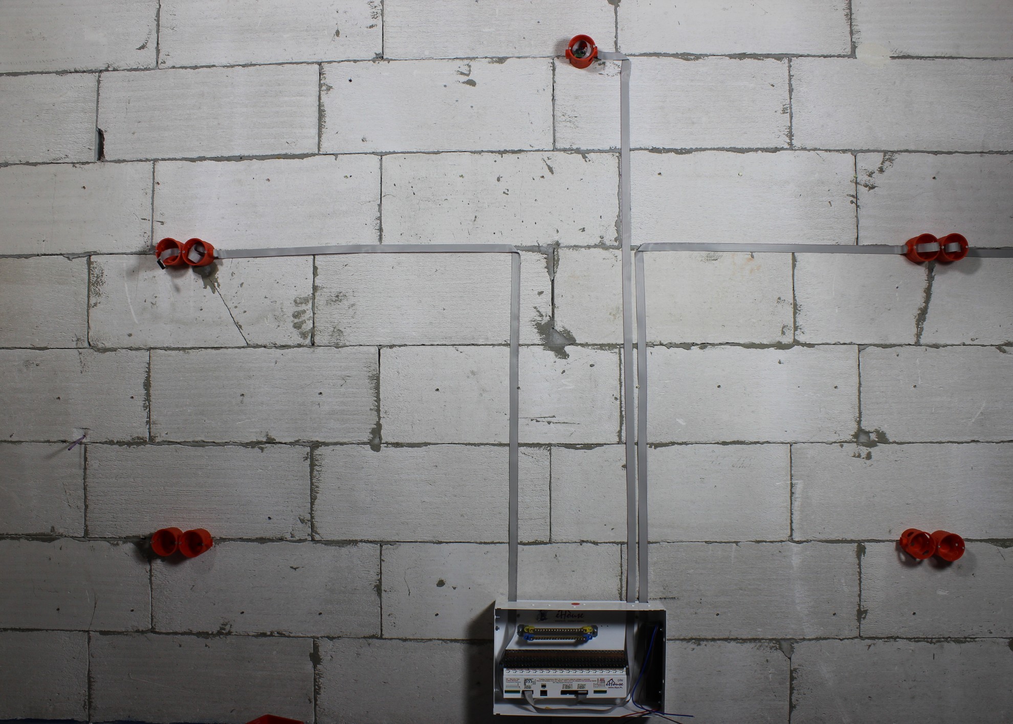
Ending with a connector and leaving the stock.
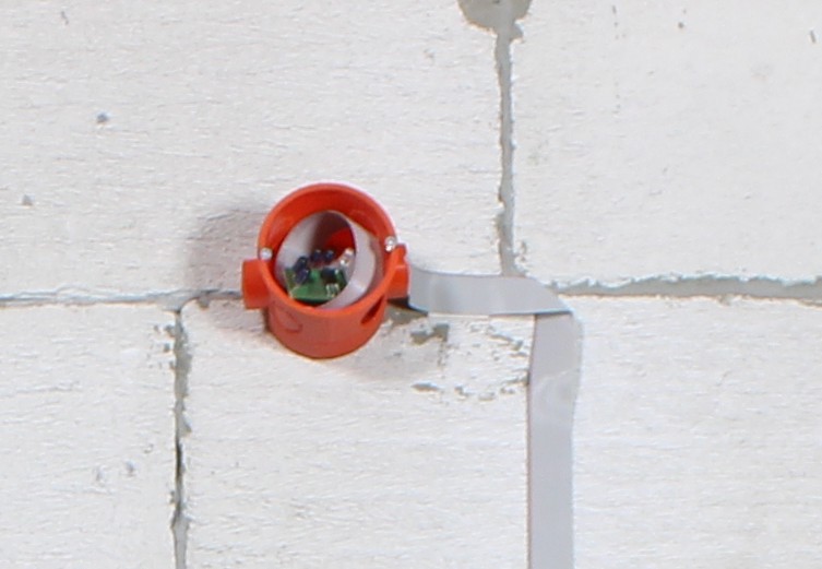
Internal view of switching station before gluing wires:
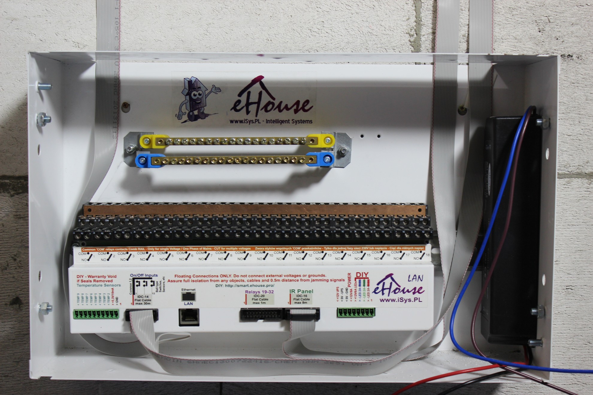
Connection of switchgear to Ethernet network UTP-8 cable (UTP) with RJ-45 connector.

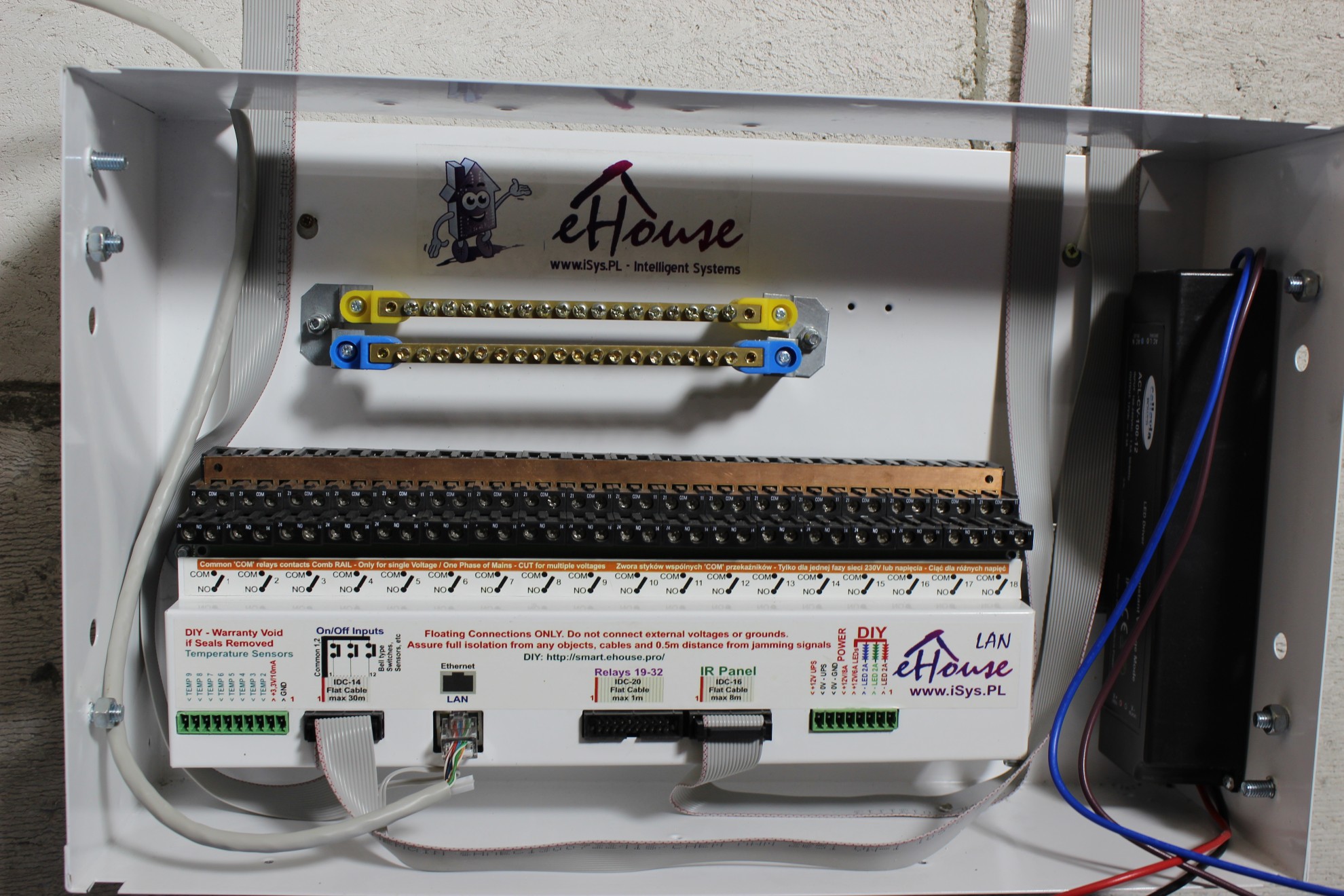
Connection of electrical devices to relay contacts:
Rail “COMB” make contact shorten of all connections (common “COM” relays) – work on one phase.
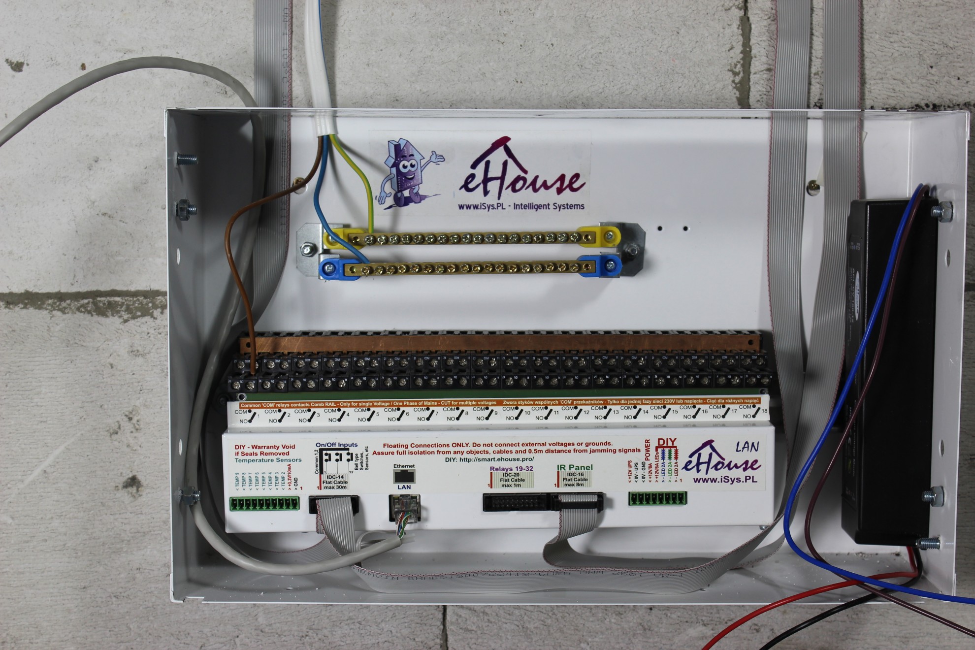
Neutral “blue” wires are connected on blue rail.
The yellow-green protective conductors are connected to yellow rail.
Electrical devices (phase) are connected to the NO contact (Normally open) of the relay.
The comb can be cut to control the devices for various voltages.
Connecting the first electrical circuit to the relay contact:
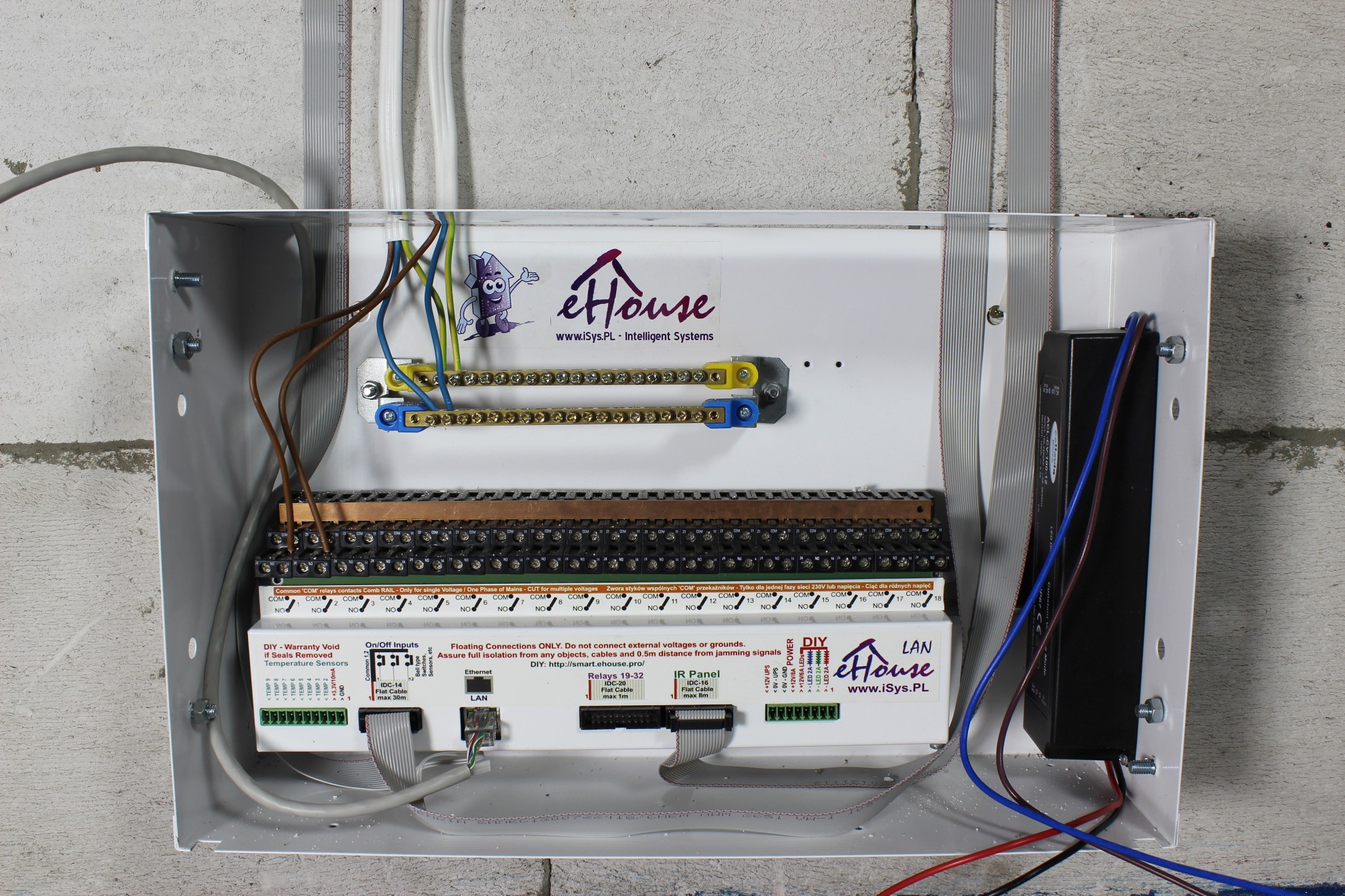
The switchgear must be protected by a over-current and differential-current fuse, placed for convenience in the central switching station and not in the mini-switchboard, due to easier access, especially when the switchgear is covered with furniture.
In order to protect against mechanical damage of flat tapes by construction crews, it is worth covering them with reinforcement mesh for expanded polystyrene (width ~ 10-15cm) and apply adhesive to styrofoam.
This will also prevent the tapes from unsticking in case they do not stick too well.