eHouse Ethernet (LAN) home automation Smart Home assembled Mini-switch board for building automation ready for connection.
In this post, we discuss connection assembled professional mini-switch board of eHouse LAN Intelligent home with “EthernetRoomManager MINI” controller dedicated to the installation in electrical fuse boxes and relay module MP-18 containing 18 relays with sockets and PCB carries out a set of low-voltage connections between the controller and relays without taking hours, tedious patching cables.

ERM-Mini controller has the same functionality as compared to the standard version of the ERM.
- 24 (*32) output on/off programmable relays with drivers
- 12 inputs on/off switch for connecting switches, detectors
- 3 dimmers LED drivers 12VDC/3A with optional optical isolation
- 10 measuring inputs
- Infrared transmission and reception for controlling the ERM and equipment Audio/Video
The only differences in the ERM in the standard version:
- more than 2 times smaller than the ERM – smaller than a standard credit card. The small size allows for vertical mounting in a standard electrical box with relays without using additional DIN rail for the controller
- no optional switching power supply
- no separate connectors for power supply and dimmer
- no internal connectors: IR receiver/transmitter, temperature sensor, ambient light sensor (available on the connector of IR panel)
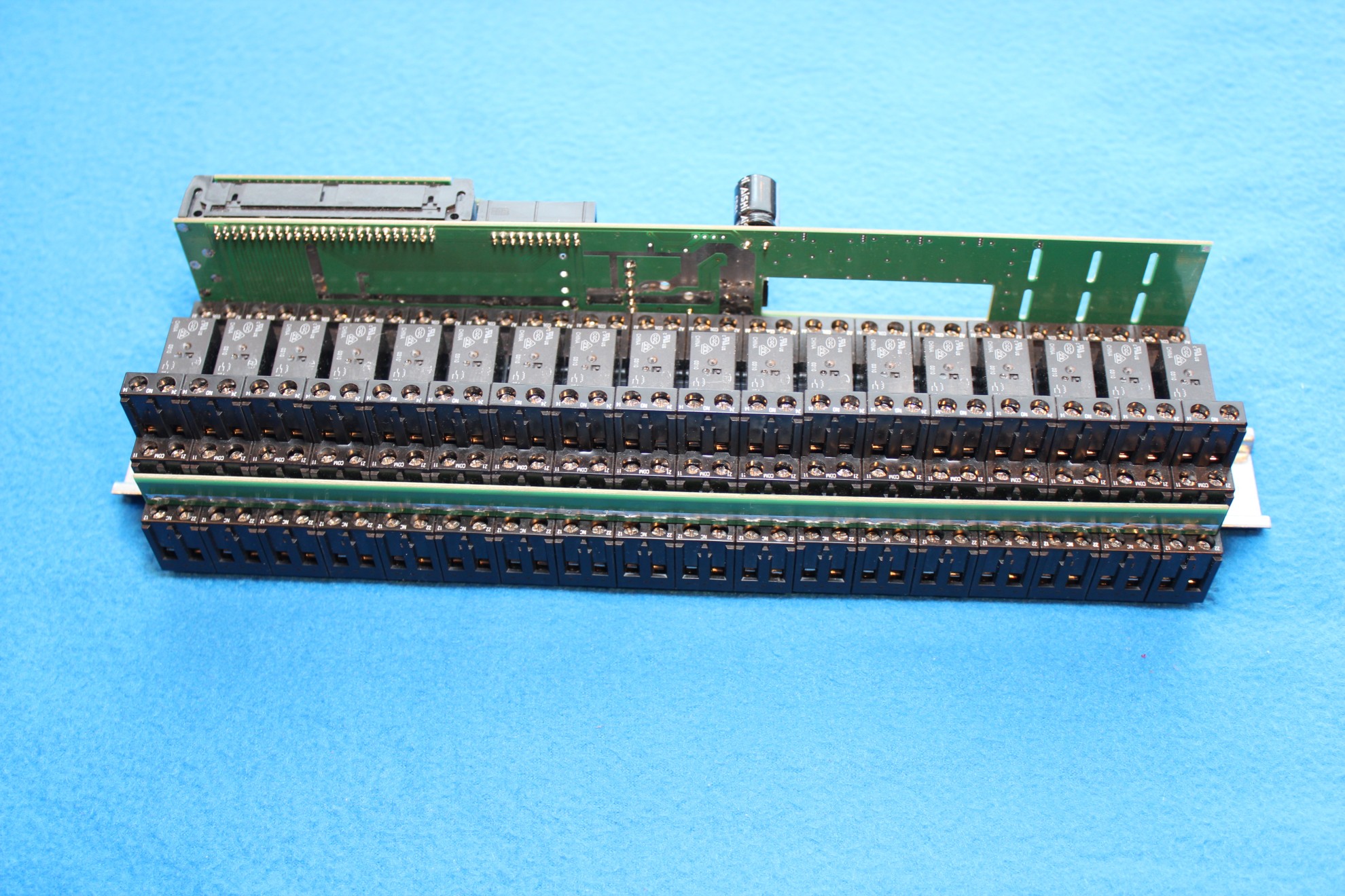
MP-18 Relay module allows you to connect up to 18 relay 230V/16A to ERM-MINI driver without the need for any additional wiring.
The controller plugs directly into a connector on the MP-18.
Contains 18 relays and sockets for DIN rail and is located on a single DIN rail of size 18 or of single modules.
The module may include optional rail to short “COM” – common relay contacts, if you turn on single voltage and phase (it could be divided for more than one power supply).
If you need to use more relays supported by the controller (up to 32) can be connected in cascade second module of the MP-18 IDC-20 tape. This requires using electrical boxes containing a minimum of two rows of 18 modules.
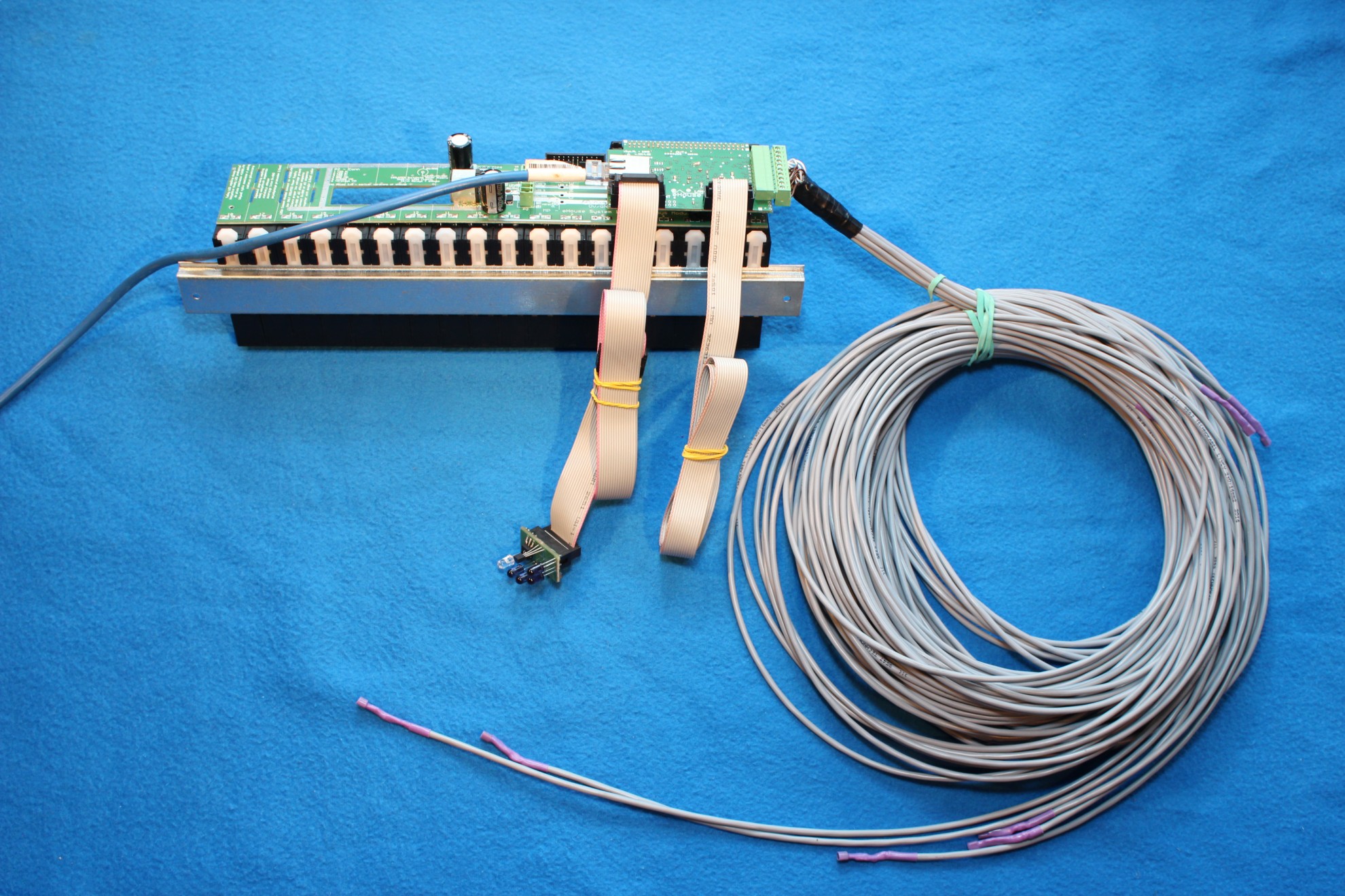
Assembled mini-switch board includes
- LED switching power supply 12V/8A enable powering building automation, all the relays and LED strips connected to the dimmer
- External infrared panel (IR Receiver & Transmitter, Temperature Sensor, Lighting Sensor) with finished wiring (IDC-16) panel (8m max) to derive it from the electrical box in front of the equipment Audio-Video
- wiring switches IDC-14 (10m) to distribute serially around the room to all switches/sensors.
You can order individually made optional temperature sensor with cable to an installation ready to attach to the controller. The standard is available 8 temperature sensors assembled with 10m of cable and connector for direct tie-in to the controller.
After the installer is required to:
- mini-switch board mounted in a room or in a controlled area
- Serial cable distribution IDC-14 switches, sensors (between cans for electrical switches)
- The distribution of cable IDC-16 for infrared panel between the controller and IR panel
- The distribution and wiring 230V and other supplies to the relay contacts
- Connect the power supply to 230V
- Connect the 12V LED strip to dimmer
- Optional additional cabling distribution of sensors in the planned space
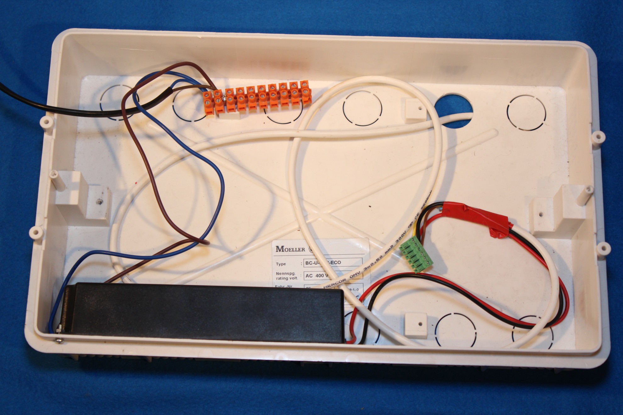
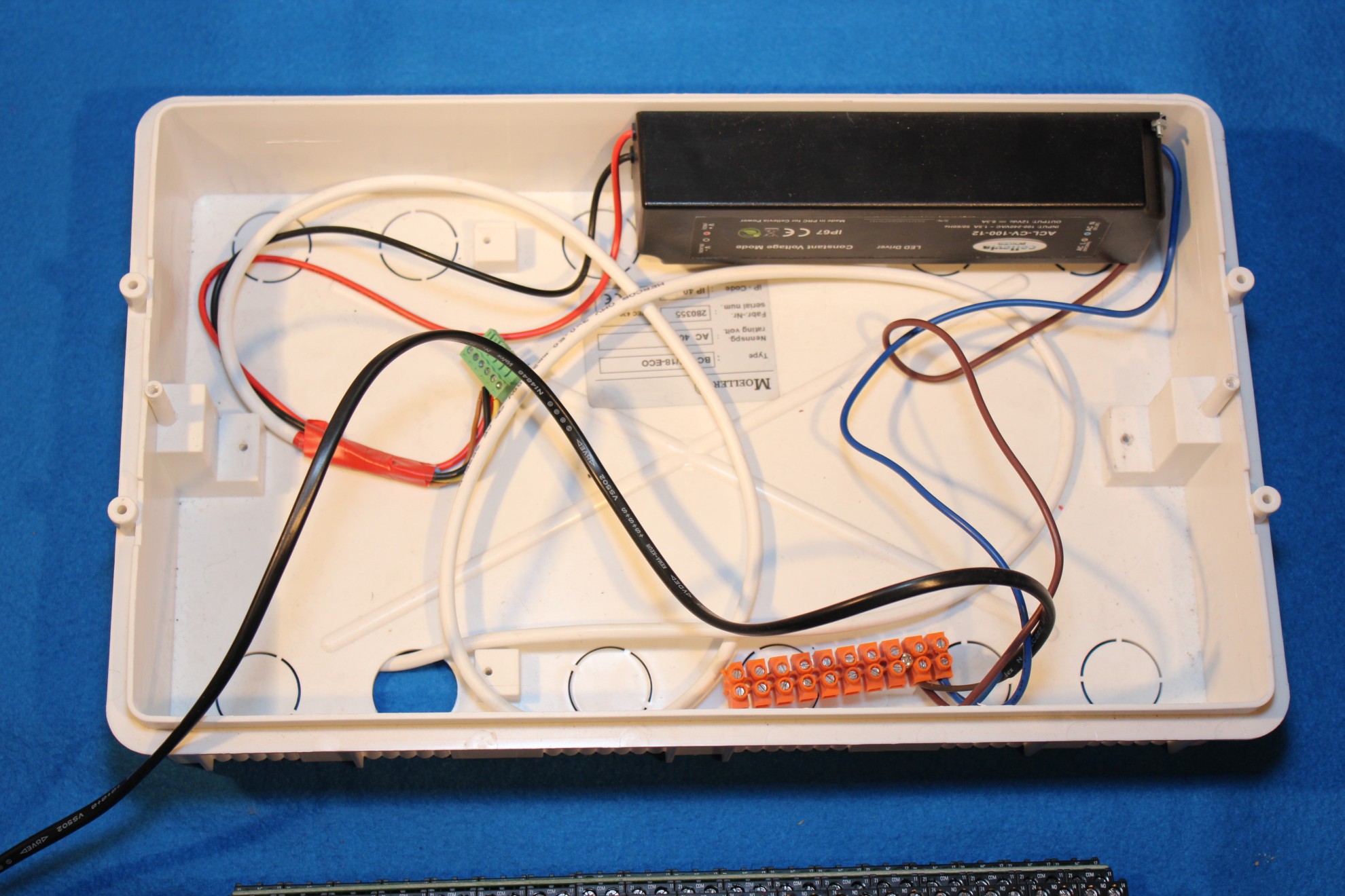
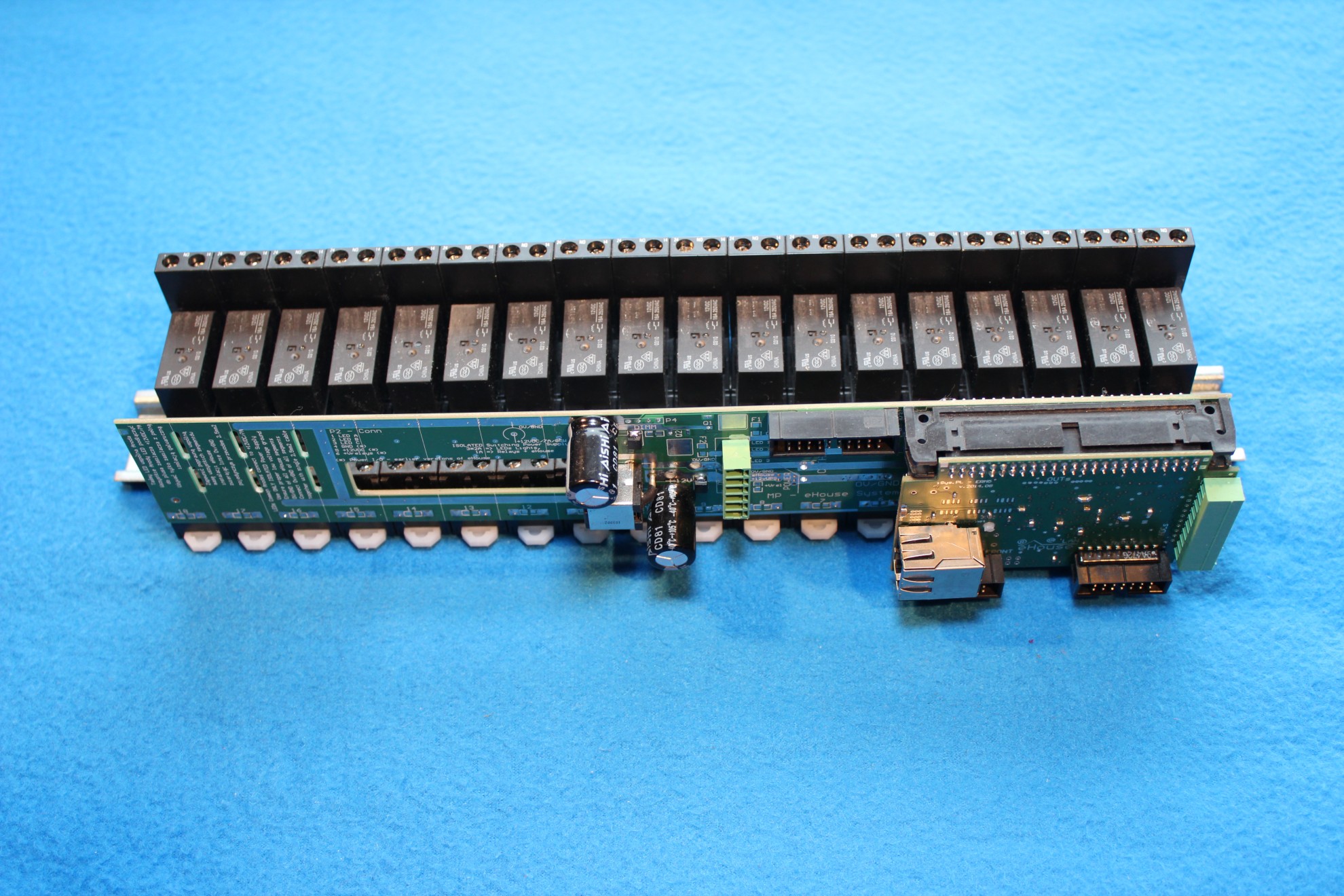
Distribution box with integrated LED pulse power supply 12V/8A Power Automation building, relays, LED strip/LED RGB.
3 * 2.5mm cable (black) is used to connect to the AC 230V and provides a connection for the entire electrical box (230V actuators). Power supply connector is attached to the 12V power connector (green DEGSON 6-PIN) which also include dimmers outputs.
Some power supplies may include protective wire (yellow-green) or not. Depending on the cable connect to the network or not.
The power supply MUST be galvanically isolated (12VDC voltage poles of 230V).
Output power connector MP-18 / dimmers:
- 1. LED 1 (RED)
- 2. LED 2 (GREEN)
- 3. LED 3 (BLUE)
- 4. GND – 0V
- 5. + 12V power for controllers (optional UPS Vups)
- 6. + 12V power for relays coils (Vdrv)
The power supply is connected to the pins respectively poles 4 (0V) & 6 (+ 12V). In the event that we have sustained-power (UPS) + 12V can hook them to pin 5.
You can connect to the distribution or LED strips LED/RGB. Cathode (-) LED dimmer terminals (pins 1,2,3), All anodes directly to +12V on power supply.
Use wires with a diameter of 4mm2 (cord) due to the high current and voltage drop on wires.
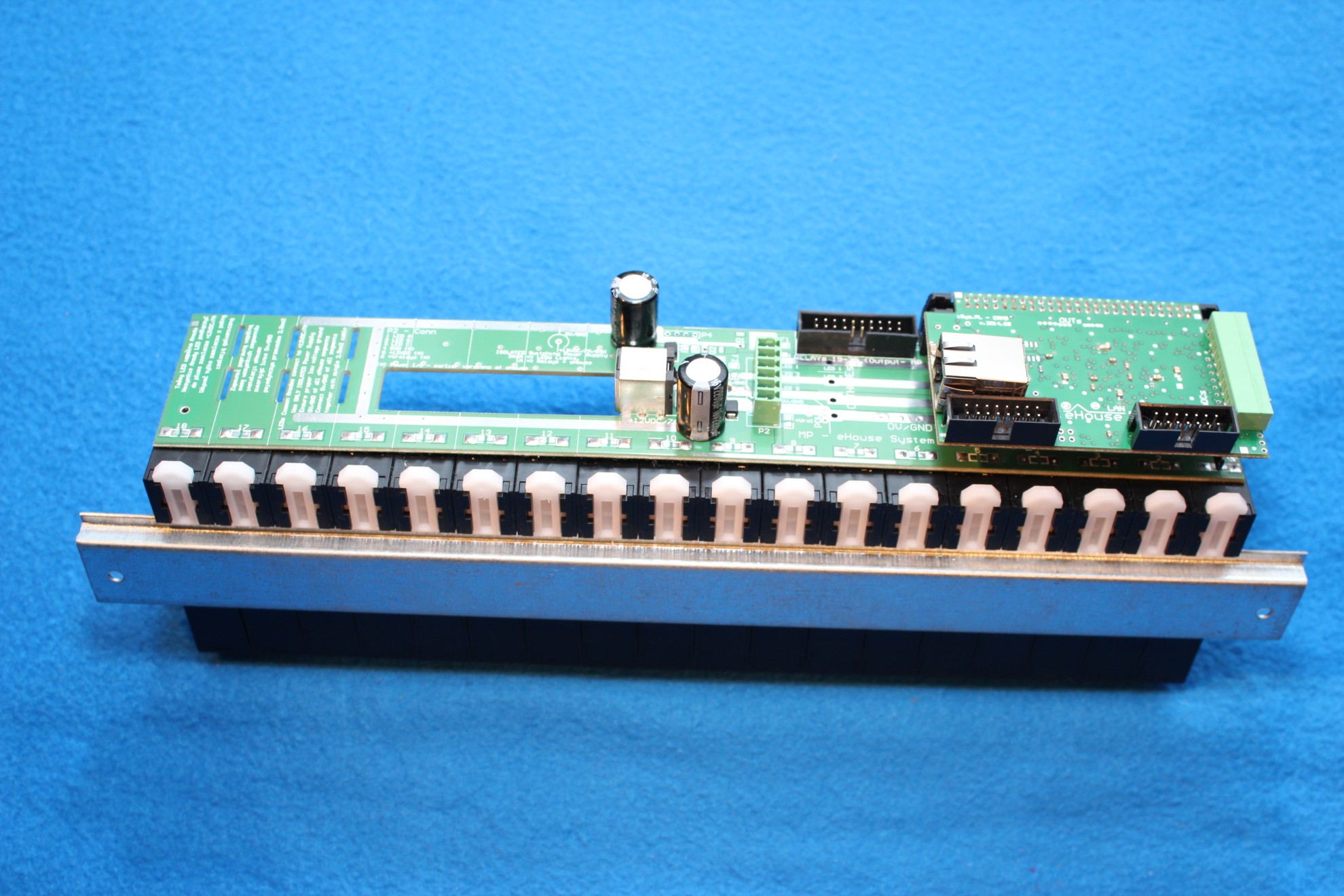
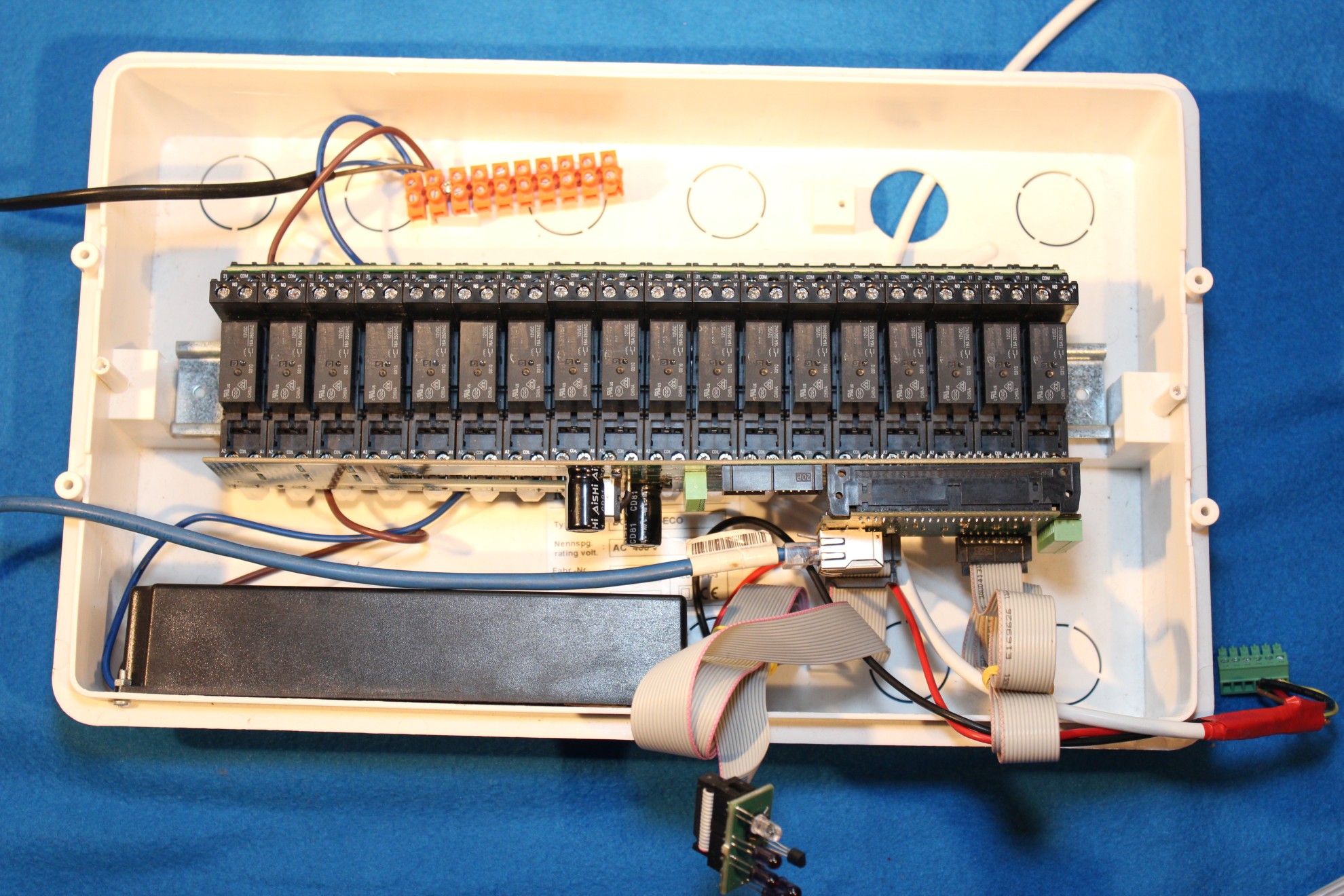
Relay module MP-18 without a plugged in ERMMINI controller
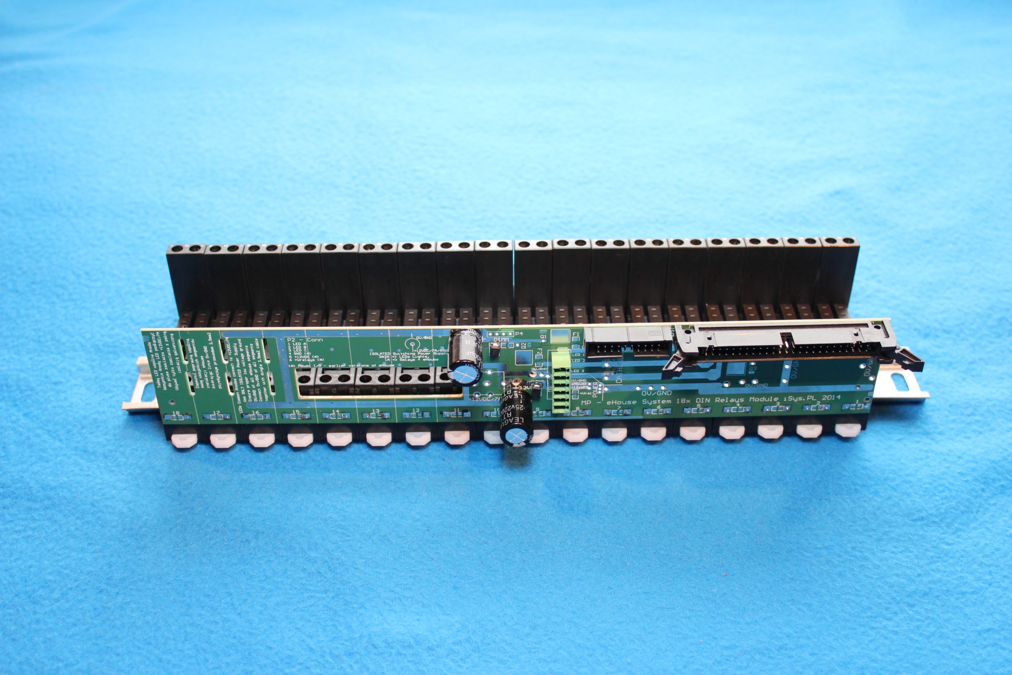
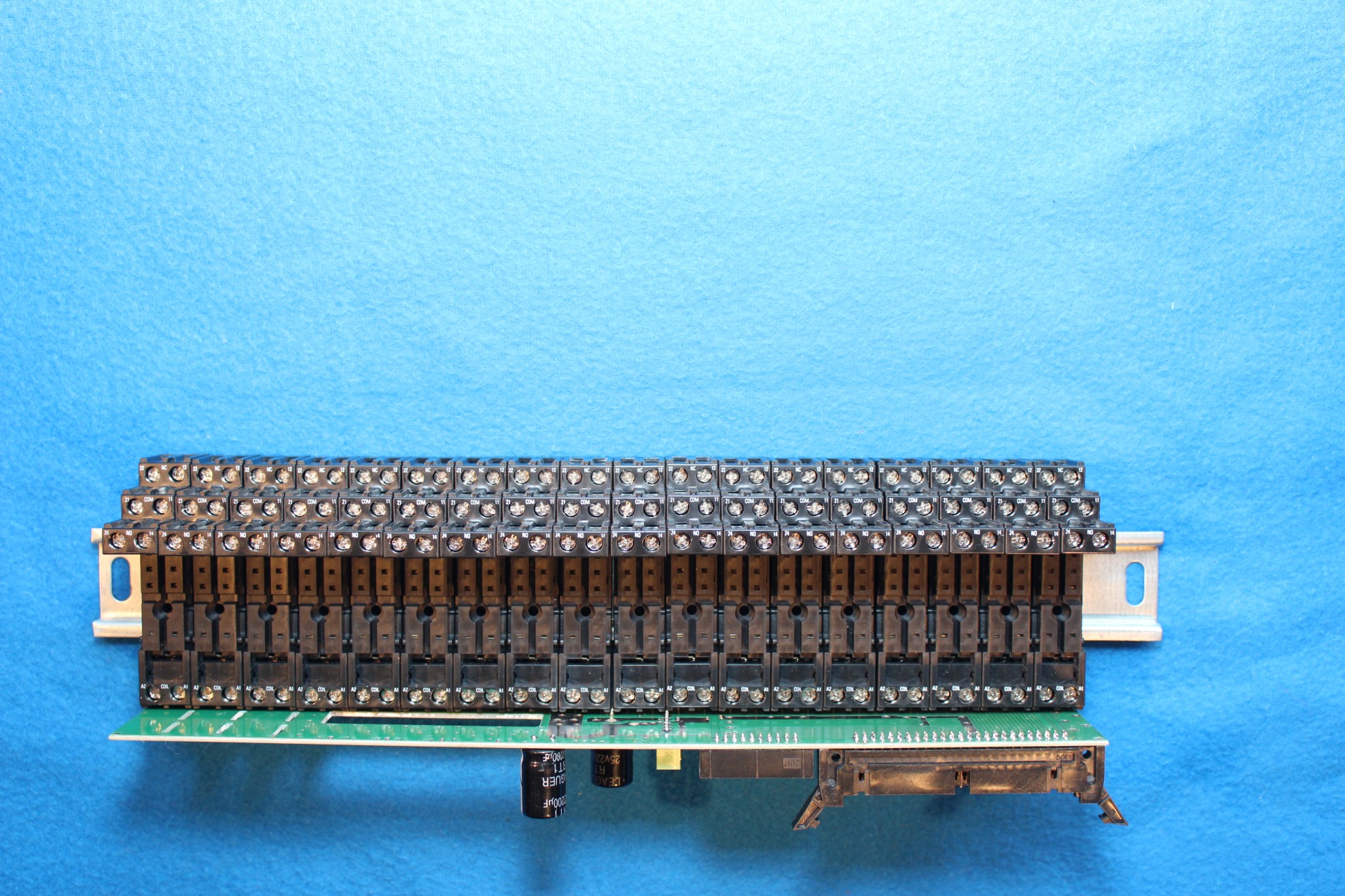
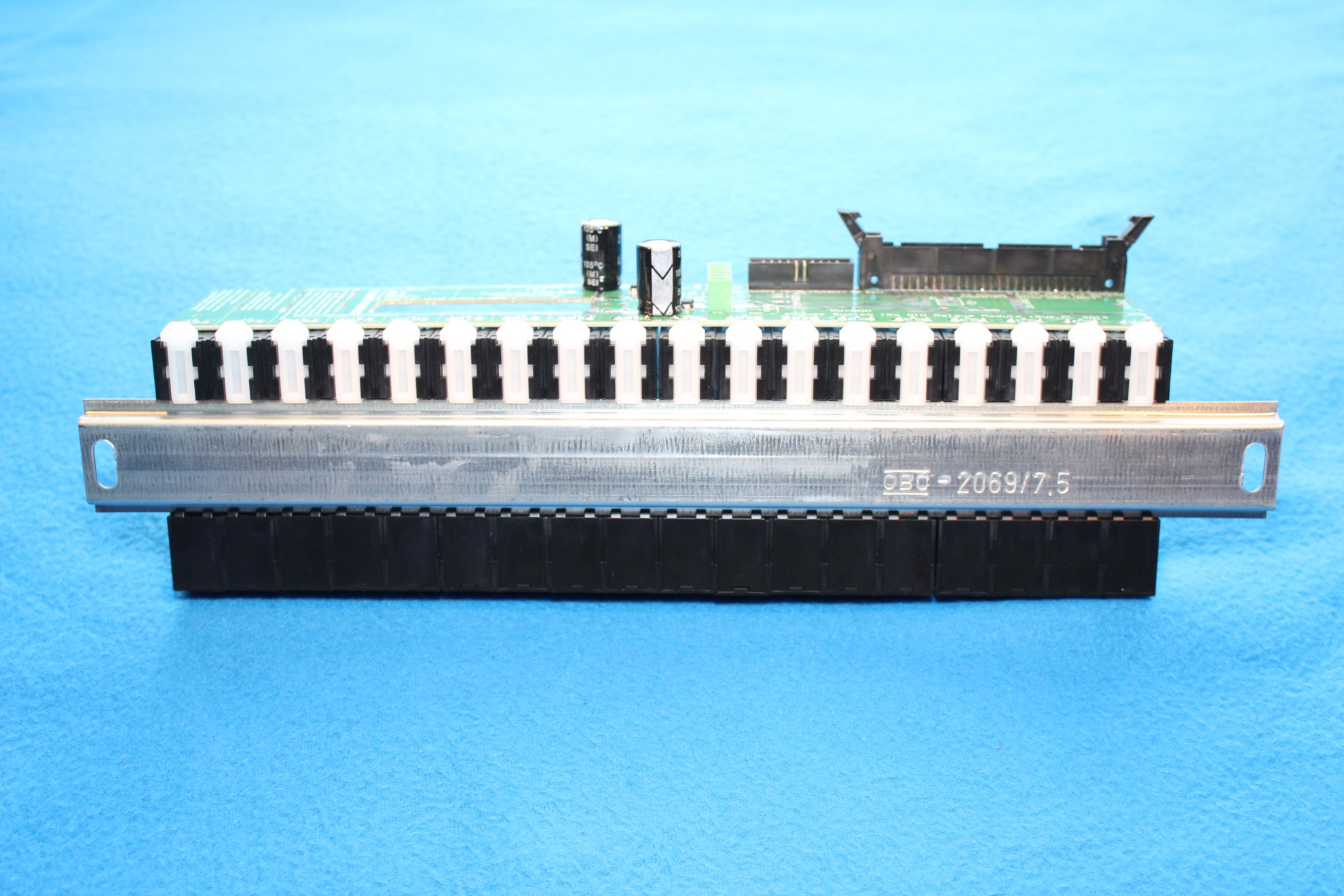
Installed optional rail for “COM” (common) contacts, for all the relays in case of a single (one phase) power supply such for all loads eg. 230V.
This rail is connected to the hot wire of 230V or other voltage.
This will reduce the time to manually shorting the contact wires which takes an extra few hours.
When a part of the devices connected to the relays working on other voltages or phase of the rail can be cut, and a further relay contact (“COM”) individually connected to the required power supply.
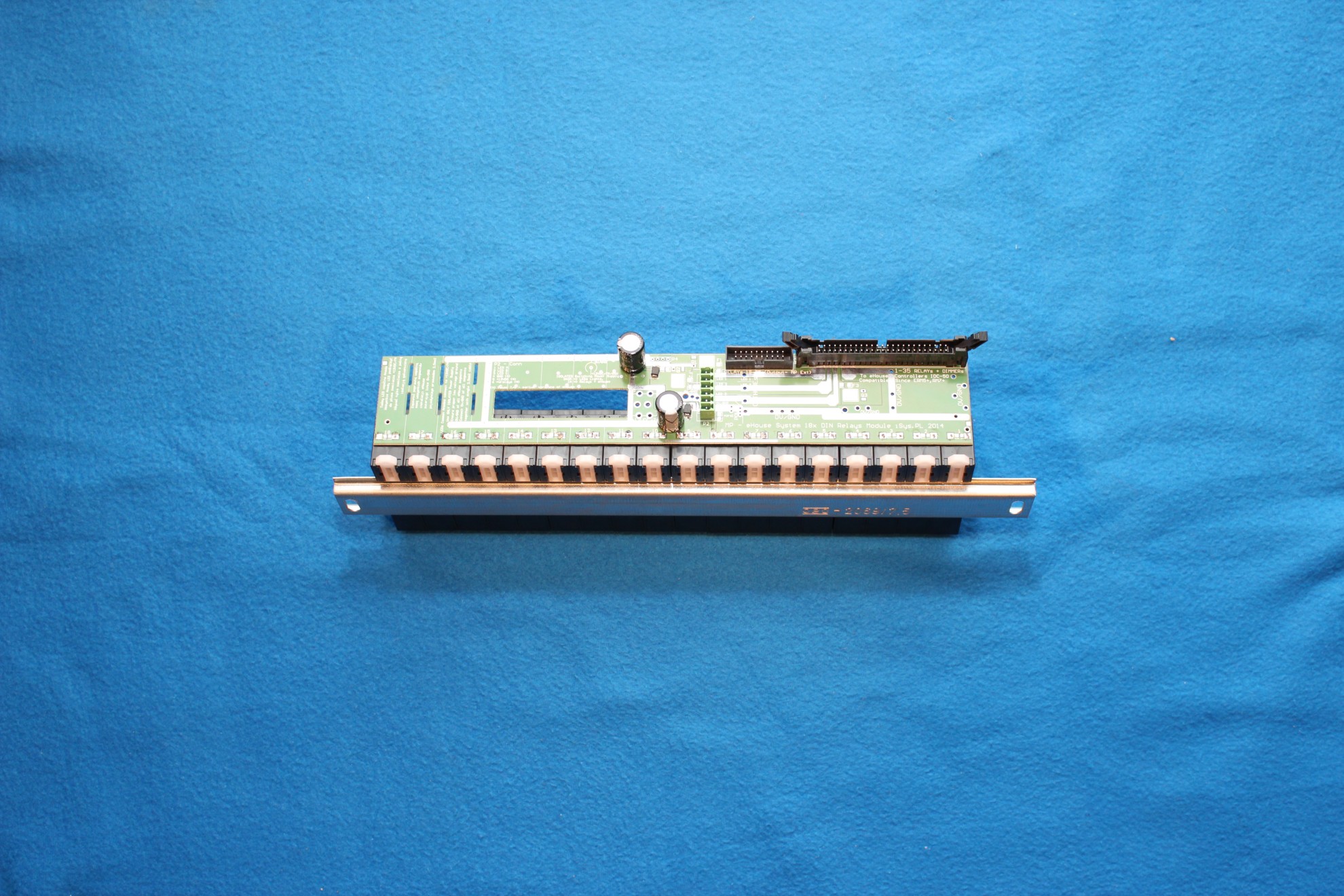
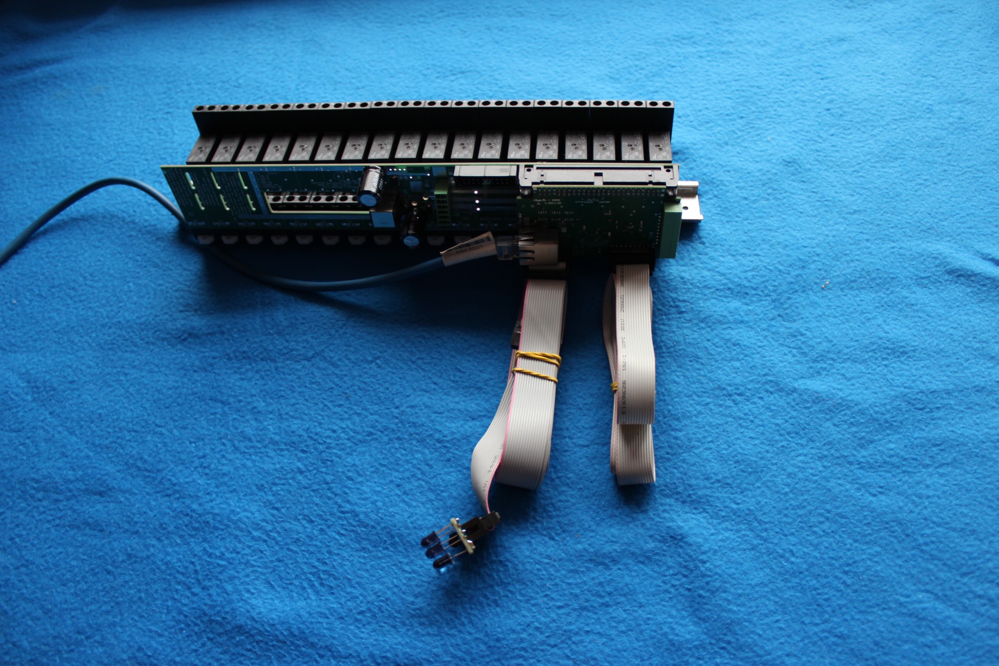
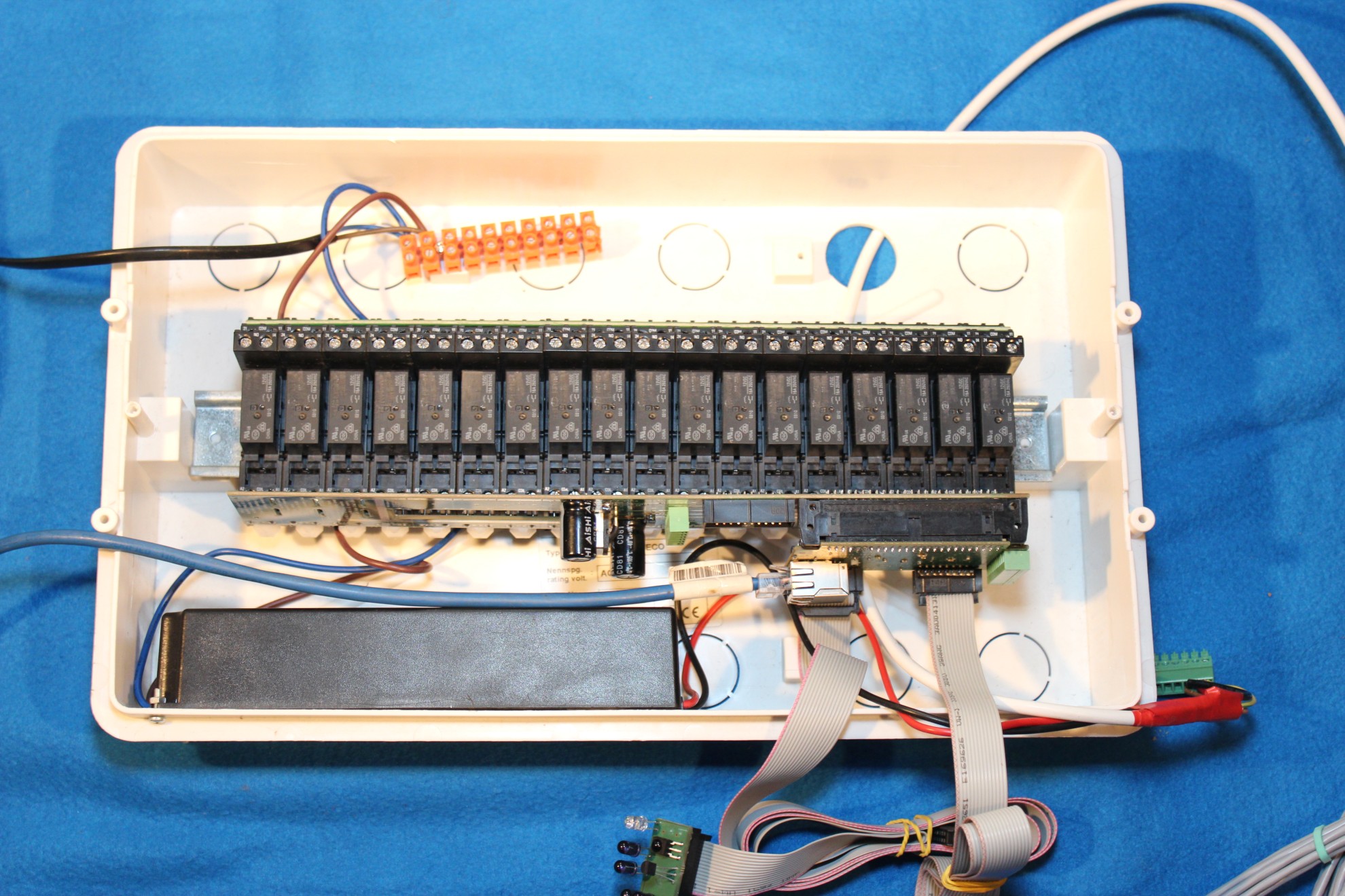
Relay Module with integrated ERM-MINI driver, which is pushed into the connector on the module relays. Is carried out in this way, a full connection coil of the relay, dimmer and power ERM.
Low-voltage wiring to connect the ERM-MINI performs identically to the standard ERM.
The blue wire UTP-8 is the standard cable for computer networks at each end RJ-45 (1: 1) in accordance with the colors (twisted pairs). It connects to the Ethernet controller ERM-MINI.
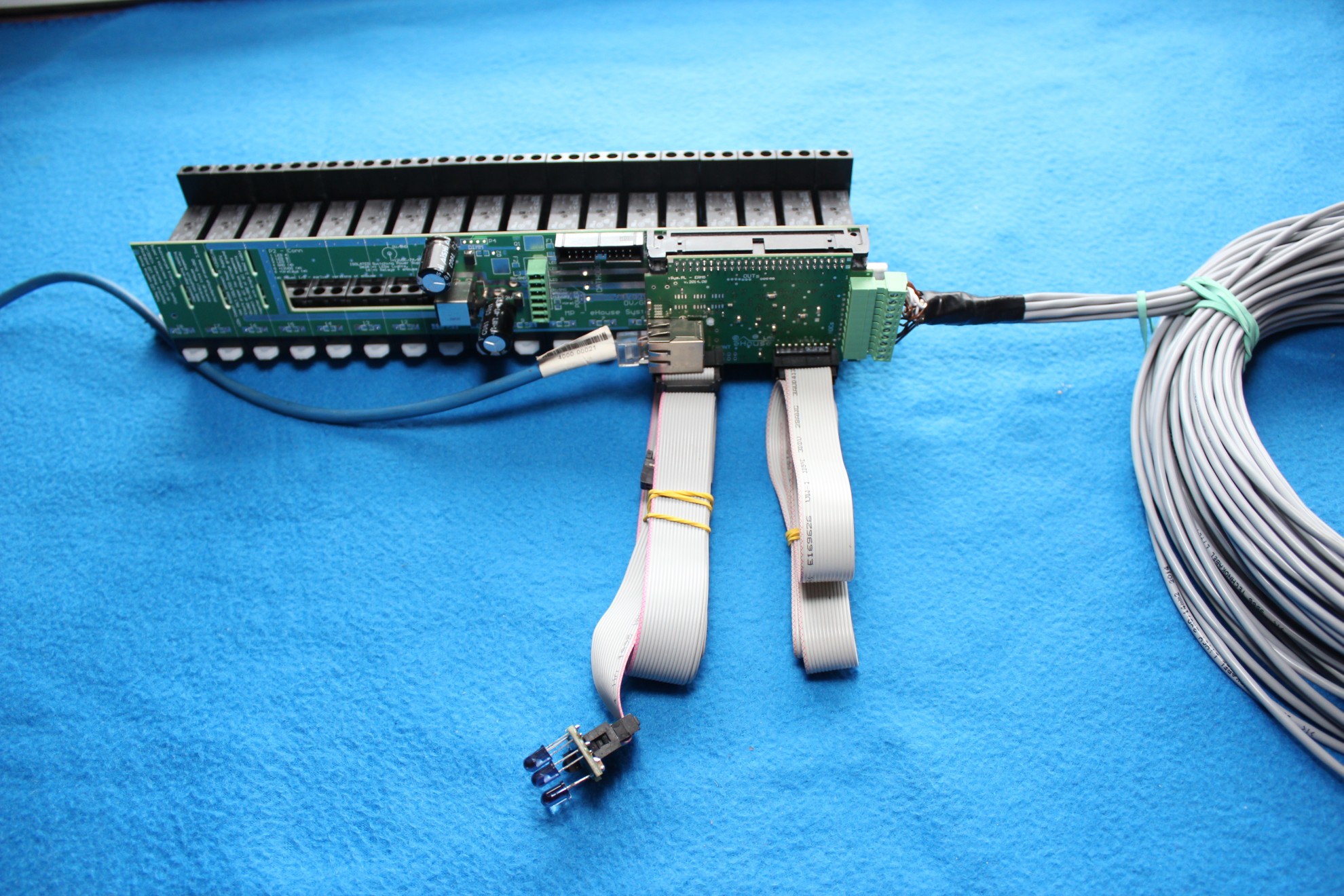
Connecting the Infrared Panel
IR panel connects with IDC-16 cables and crimped IDC-16F (female) connectors (1: 1). The maximum cable length is tested 8m. Critical here is the infrared signal transmission equipment Audio-Video. Different devices (transmitter codes) can be sent correctly or not, depending on the individual pulse times. Infrared panel should be placed in front of the planned equipment Audio-Video no more than 8m, at least 1m from the side wall assuring nothing stood in the way of the light beam.
IDC-16 flat cable does not require forging grooves just stick it to the wall before plastering. It should be led him away from interfering cables and signals. Do not connect any other voltages to the cable.
Because of that the panel also includes a temperature sensor, do not install it 1.2m height, if we intend to correctly measure the temperature. Alternatively, you can connect an optional temperature sensor and place it in the desired location.
Connecting switches, sensors
Wall switches and sensors connected to the cable IDC-14 from the clamped IDC-14F connector (female). Wire leads in series between electric cans on planned switches and sensors. A loose loop of cable needs to be done in the can to tighten IDC-14F connector for future connection of wire switch.

Connecting an optional temperature sensors or other.
Optionally, you can install additional sensors, eg. Temperature (max 8). You can do ityourself or order desired acording to specifications (length / quantity).
The rationale in this case is the execution of individual heating control in public integrating all functions such as heating. For the floor.
+ box before submitting a Building Automation
eHouse Home Automation can be installed in a box on a DIN rail or without (as far as we use rail for “COM” terminals to keep relays toogether).
In the second case, eject/remove from the DIN rail relay sockets and screw the base to the bottom of the box so that significantly reduces height taken up in the box.

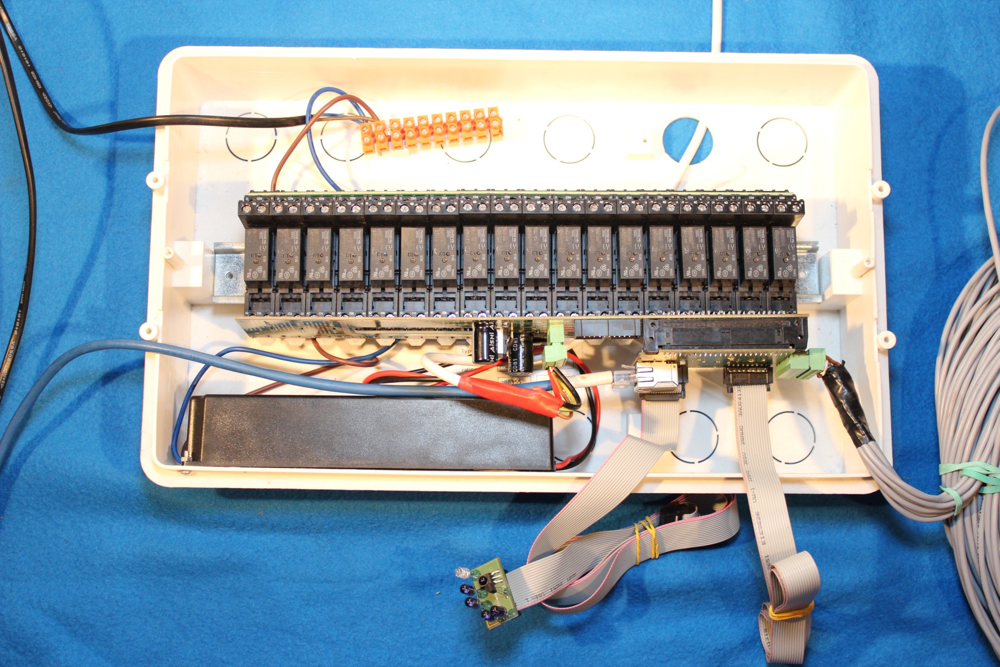
complex mini-switching box eHouse LAN
Bear in mind that all cables included to the box from the bottom of the box through the mounting holes and not as shown in this picture for better view.
It should also take into account the location of the 230V cables and keep them as far away from the low voltage wires.
It is not allowed to connect any external voltages to any pins of controller. The individual segments are separated from each other by the power supply and Ethernet trafo connection so do not short the masses or power voltages. In this case, the drivers are galvanically isolated from each other, and even the most serious failure of one does not cause damage to other eHouse LAN system.
The only exception is the case of application of the common UPS to maintain voltage drivers. It is necessary then the common short one wire of all masses (GND – 0V) and the second voltage + 12Vups.
mini-switching board Schematic of EthernetRoomManager Mini:

Smart Home eHouse LAN switching mini PDF schematic