Ethernet eHouse Intelligent home schematic – version 2014
Smart Home eHouse version of Ethernet is the optimal version for use in residential buildings, offices, hotels, guesthouses in decentralized (Comfort) installations.
Version comfort means the use of a few up to several RoomManager controllers for most natural division of the building by rooms ( EthernetRoomManager ).
Despite more controllers and their costs, reducing the consumption of 230V wires, labor, complexity of the installation so that the final expenditures for automation could be similar.
Room controllers include a large number of hardware resources:
- Ethernet interface for direct operation on the LAN
- 24 – 32 programmable digital outputs (ON/OFF) to turn the mini switching relays
- 12 programmable digital inputs ( on/off ) to assign eHouse system events lunched on changing state
- IR transmitter for control of audio / video, Electronics etc. – learn and sending control codes
- IR receiver to control rooms ( EthernetRoomManagers ) directly from the remote control SONY
- 3 Built-in LED dimmers or 1 LED-RGB with drivers 12V/3A with opto-galvanic isolation
- 1 measuring input for light sensor
- 7 measurement inputs for temperature or other voltage sensors operating in the (0 , 3v3 )
- Ext containing serial ports to install system extensions, wall panels, card readers , etc.
changes in hardware compared to the previous variant EthernetRoomManager:
- Changing the ADC connector ( measuring inputs ) IDC-20 connector to a single 10 pin (slide + screw ) . Allows easier installation of shielded cables for sensors
- Built-in 3 drivers dimmer LED 12V / 3A with opto-insulation and fuses ( optional)
- No 4 -pin power connector – power driver with IDC – 50
- Changing the Ext ( Panel ) of IDC-16 IDC-24.
- change of location of connectors and sockets for mounting in housings fuse boxes Moeller “BC-U-05.01-TW-ECO” ( 5 fuses with window ) and DIN rail enclosures.
Ethernet controllers allow room management:
- control of any electrical equipment ( on/off )
- measurement and temperature control/management, lighting and other physical values
- implementation of the standard electrical switches to control the system
- allow you to connect directly decorative LED strip or LED – RGB ( 12VDC max 3A). LED-RGB strip must be configured to work in “common anode” . Tapes require an external power supply .
- contain sophisticated scheduler – calendar 128 items
- contains 24 customizable programs work out and LED dimmers
- contains 12 configurable measurement programs / regulatory
- allow the creation of “base” 255 infrared codes for HiFi equipment to transmit
- allow the creation of “base” 255 remote control codes and assign them to eHouse events
Whether we install comfort variant of eHouse, installation consists of a dozen or so independent low voltage (up to . 12VDC ) installation segment .
The segment consists of :
- driver ( EthernetRoomManager or other)
- Relay for DIN rail and possibly the relay module ( to facilitate their connection ” Patching ” IDC-50 tape)
- LED lighting / LED – RGB
- switches and sensors (on / off )
- sensors ( analog )
- power
Each segment is connected to a switch / router LAN UTP cable – 8 . Additionally, it is powered locally or jointly with other segments .
There are three sources of power for each segment:
- power “electronics” driver – +6..12VDC (DC) preferably with backup (UPS)
- power relays depending on their voltage (+5V or +12V). In the selection of the power supply can be used with higher voltage of +1V with respect to the voltage relays .
- power LED and LED-RGB executed locally shortest and thickest wires ( 4mm2 min ) .
In principle, the use of LED lighting implies the use of a dedicated power supply LED 12V/150W LED as close as possible due to large losses in the wires. It can also be used to power the relays 12V .
Installation diagram of one segment is presented below : 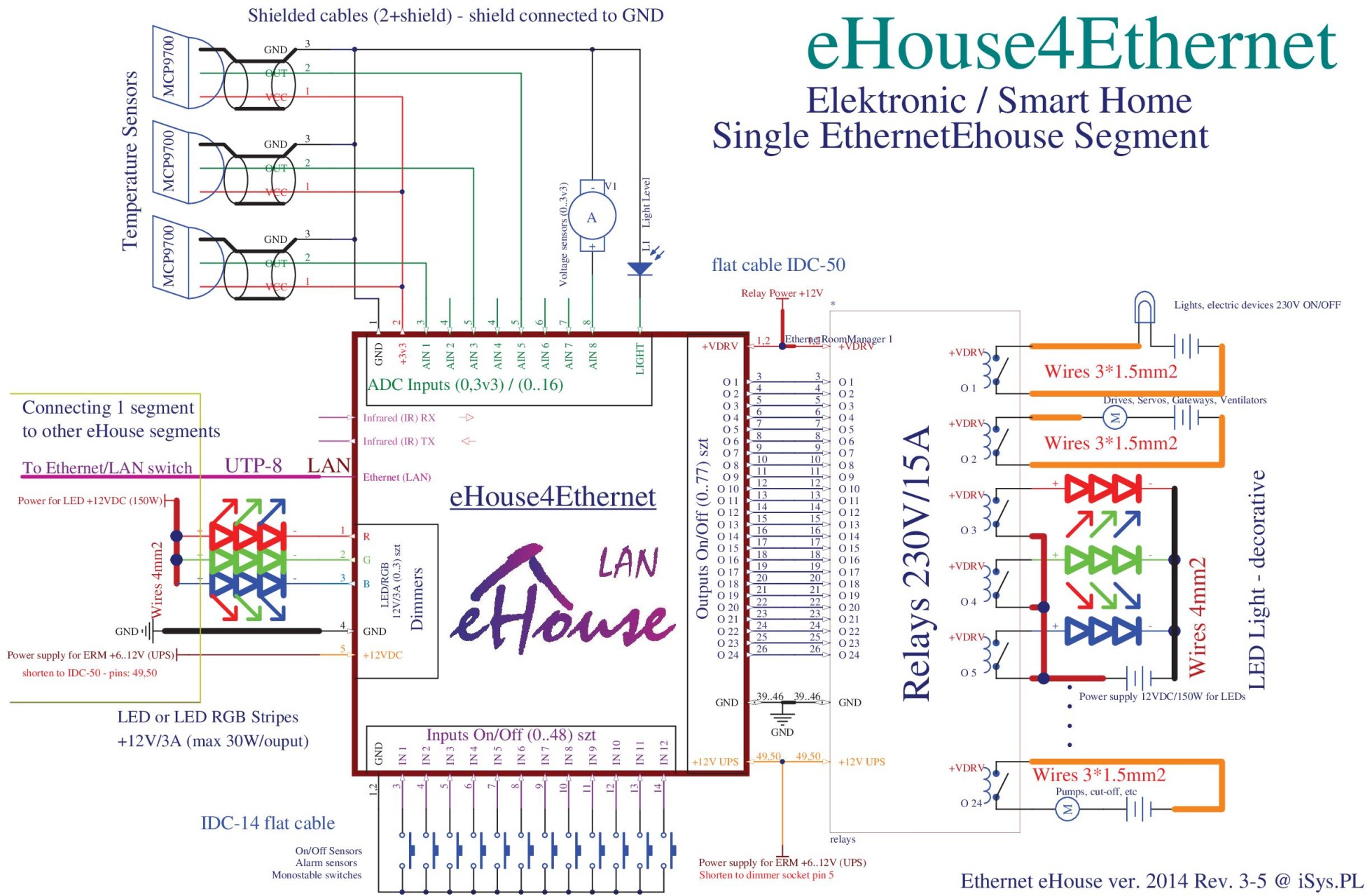 For more information about the driver : Smart home Ethernet – EthernetRoomManager Smart home EtherneteHouse Connecting the controller ERM .