eHouse home automation smart home equipment intelligent switching center, connecting the UPS, alarm sensors and inputs and electrical equipment regulations.
Description is an extension of the existing articles on eHouse.PRO system – building automation .
eHouse.PRO assemble the central switchboard.
eHouse.PRO Building automation
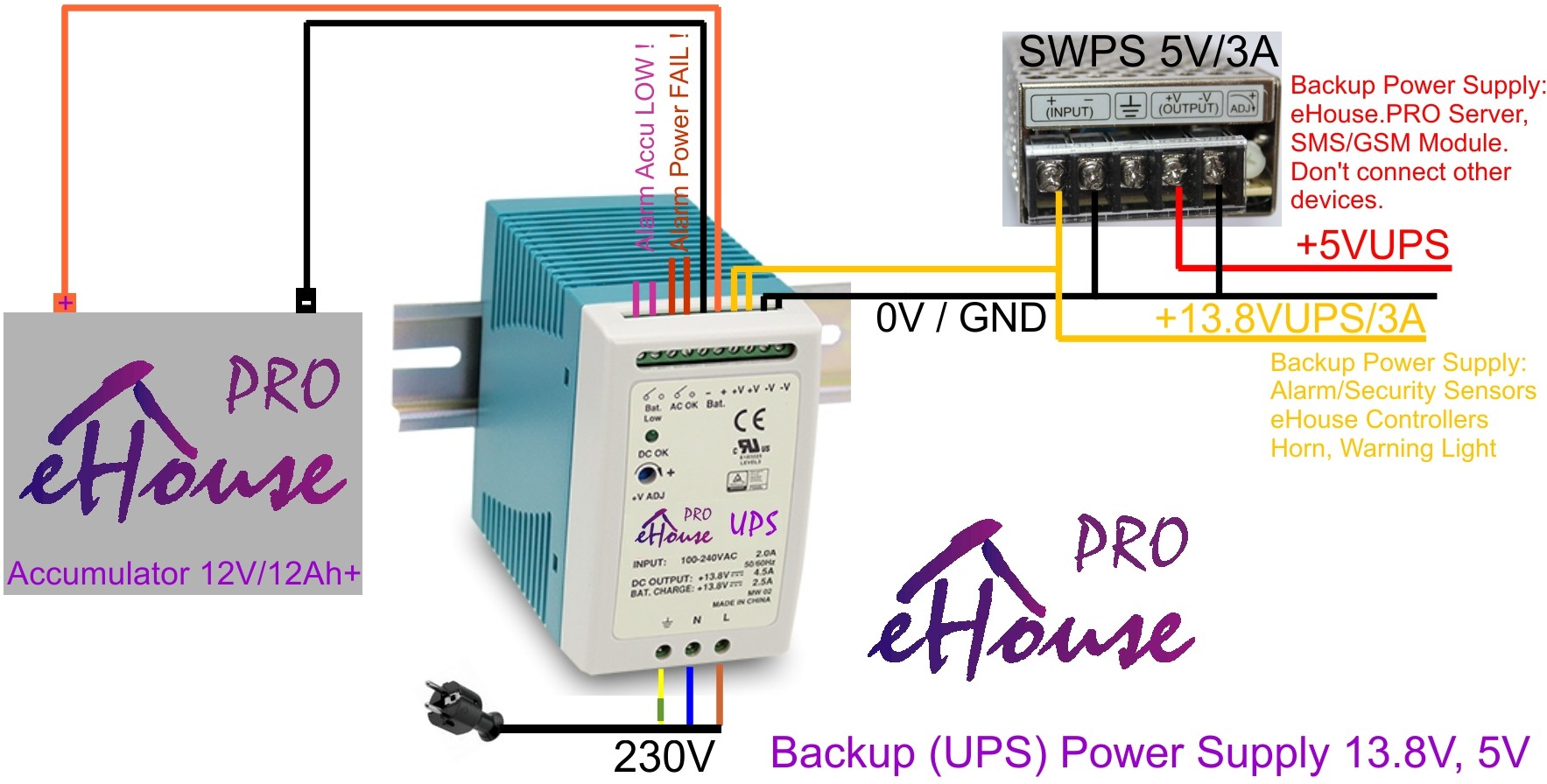
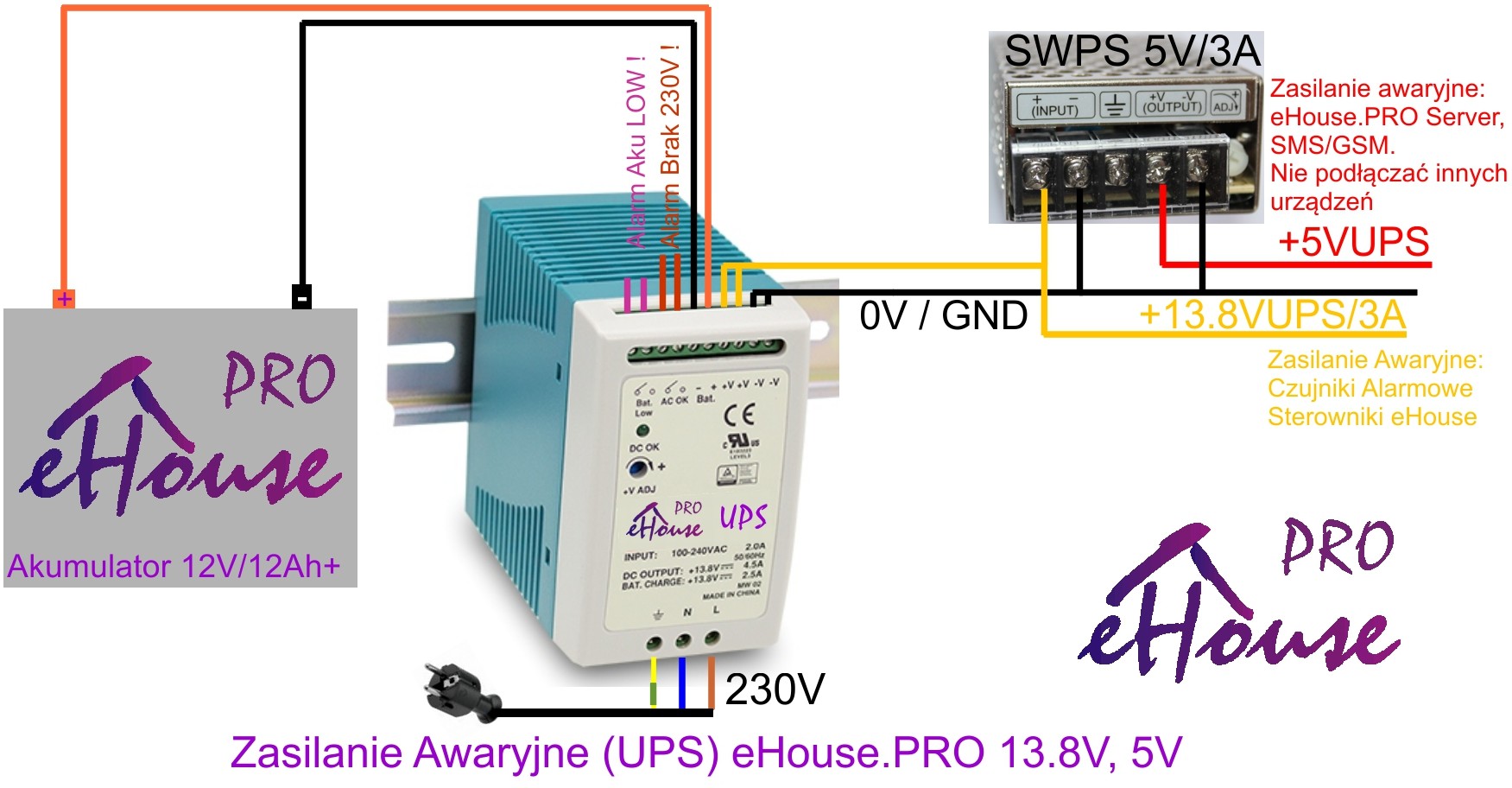
Connecting the UPS 12V (13.8V) and UPS 5V
Power Supply (UPS with backup power) eHouse.PRO system is used because:
- The built-in alarm functions in controller
- uninterrupted power supply alarm sensors 12V
- uninterrupted power management for microcomputer 5V
- protection against transient voltage outages, surges, etc.
To reduce the cost of the UPS 12V and 5V power supply uses a dedicated system comprising:
- Switch Mode Power Supply UPS 12V / 4.5A+
- 12V/20Ah+ Accumulator
- DC 12V => 5V/3A+ switching power supply
In another configuration, operating costs and spaces of accumulator would be doubled. We provide wiring diagrams and installation in Polish and English to print out.
Available patterns can be printed as labels and attach to the corresponding elements in the eHouse.PRO distribution box which greatly facilitates installation, service, revision.
Power Scheme UPS 12V and 5V:

PDF
Do not connect/short-circuit any of the masses, in a way other than what is shown in the diagram. The power supply is galvanically isolated and on the housing box distribution center there is the potential protective conductor 230V / 400V (yellow-green wire). Short to low voltages can cause permanent damage to the entire electronics in the event of an overvoltage or turn on the system.
Voltage 12V (13.8V) is used to power the UPS alarm sensors (connection to the RJ-12 outputs for expansion modules).
eHouse.PRO Controller – microcomputer Linux are powered from 5V UPS.
UPS power supply is used for powering only critical eHouse.PRO system components and not use it to connect other loads (eg relays). Even in the case of a large power supply UPS, significantly reduced operating time of battery backup, which is a very critical parameter for the alarm system. The relays should be supplied with an additional power supply of 12V / 3..8A without sustaining tension.
UPS has 2 alarm outputs indicating:
- Low battery
- no voltage is 230V
They can be connected directly to the alarm system (the alarm inputs eHouse.PRO), so we can get the power lack notification via SMS.
eHouse Building Automation
Connecting devices implementing the relays

PDF
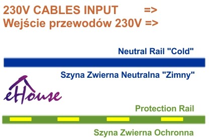
relay contacts of MP-18 Relay modules – are routed outside the shield/cover in the form of bolted connections (once at installation) to the sockets. The relays are interchangeable and can be changed in the socket in case of damage. On the electric box there are rails – bus terminal for neutral and protective cables for all 230V wires.
Contacts Common (COM) relay can be shorted with a copper bar. It can be cut (divided) into any number of segments to connect COM terminals to different phases or voltages. Wiring diagram of a single actuator or a 230V socket is shown.
In normal mode, the load is connected to the terminal NO (normally open) which means that the inclusion of a controller output corresponds to turn on the device.
If you want to get a negative (opposite) logic we can use terminal NC (normally closed), then the output on driver turns off the electrical device connected to the circuit.
Description rails make contacts Neutral and Shelter:

PDF
Track neutral (blue) 230V – is connected to the blue wire 3-wire electrical cord 3×2.5mm2 3×1.5mm2 cable to the receiver or energy or electrical outlet
protective splint (yellow) 230V / 400V – is connected to the yellow-green wire – 3-wire electrical cord 3×2.5mm2 3×1.5mm2 cable to the receiver or energy or electrical outlet
NO rail (copper) to a single phase 230V if all devices are powered from 230V – is connected to the brown or black cable to the power supply circuit safety (redundant fuses and residual current circuit breakers). You can also connect to other voltage rail disconnecting wires from neutral and protective rails.
pin relay contact NO or NC is connected to the black or brown wire of the electrical wire 3 3 * or 3 * 1.5mm2 to 2.5mm2 energy receiver or electrical outlet.
Building Automation eHouse.PRO connection of inputs

For ease of installation eHouse.PRO – intelligent building uses RJ-12 connectors to connect alarm sensors, switches, sensors, reed relays etc. Each input is connected to the RJ-12 (6 pin) to form a “switchboard relay “analogous to a telephone. This greatly facilitates professional installation, dismantling, maintenance or change the number of inputs. Connector includes a set required for each detector alarm:
- 12V power supply (UPS 13.8)
- alarm input (without the need for parameterization or polarizing resistors)
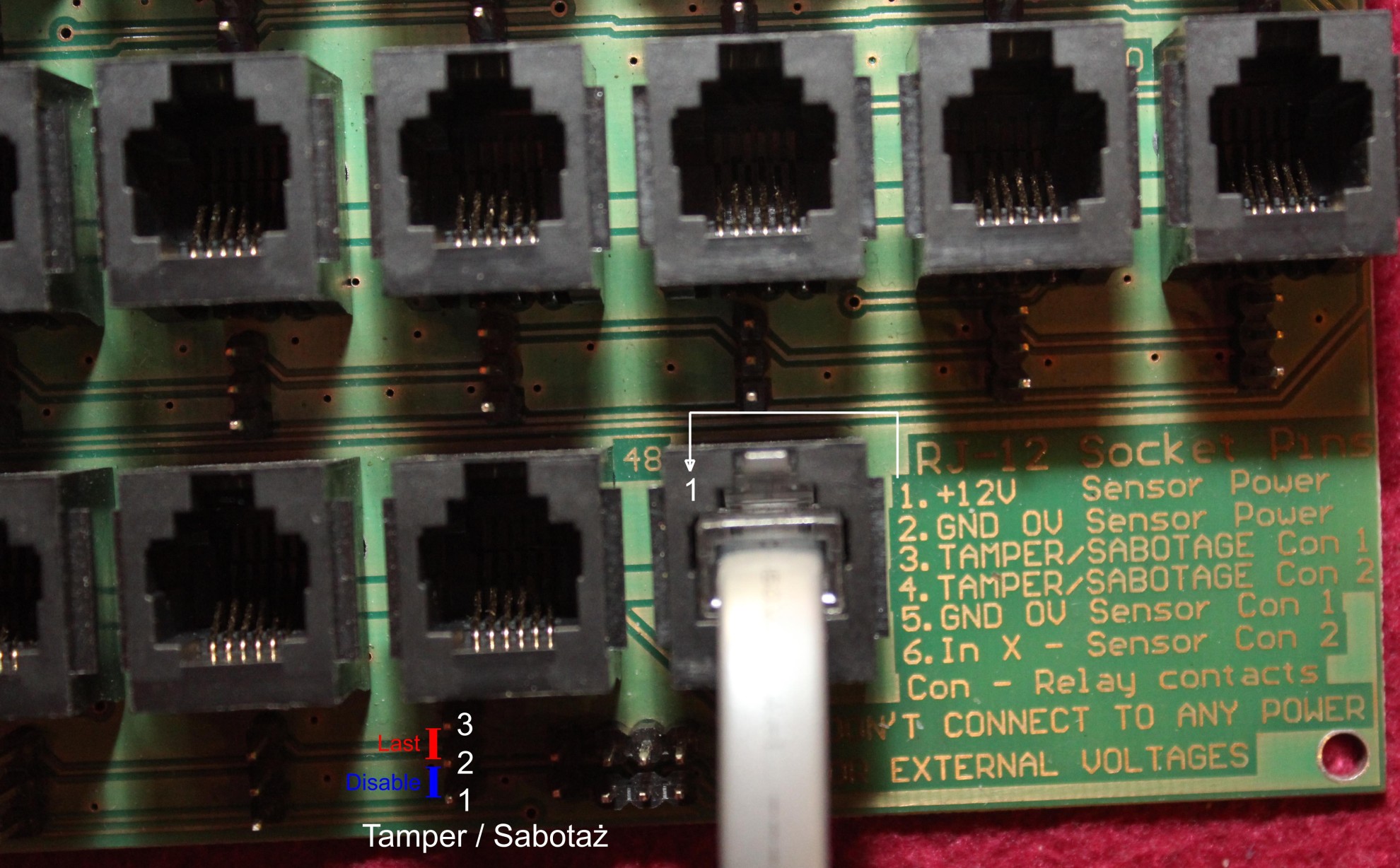
- Tamper input – Sabotage (without the need for parameterization or polarizing resistors)The figure marked the first pin for each input (RJ-12).
Pin assignment RJ-12:
- 1 – + 12V (UPS 12..13.8). Power Detector Alarm (+)
- 2 – GND – 0V. Power Detector Alarm (-)
- 3 – TAMPER – Tamper A contact. All connectors sabotage connected in series. Connector sabotage may be short-circuited by jumpers (3 pin) – 1 pin soldered square box.
- 1-2 position – short terminals TAMPER – Tamper (AB). the figure marked blue (Disable)
- 2-3 Position – Last sensor terminals Tampere. The figure marked red (Last)Do not connect any parametric or polarizing resistors or other tensions.
- 4 – TAMPER – Tamper B contact. Do not connect any parametric or polarizing resistors or other tensions.
- 5 – GND – 0V. Contact (-) detector alarm. Do not connect any parametric or polarizing resistors or other tensions.
- 6 – Input X . Contact (+) detector alarm. Do not connect any parametric or polarizing resistors or other voltage.

