Home Automation eHouse Connecting the Demonstration , Evaluation
Smart House , Home Automation eHouse can be tested using the module smart home Demo .
Demonstration module requires +12V power supply computer power supply preferably with a computer , which connect the entire system , using standard PC power connector ( 4Pin ) .
To test eHouse controllers (HeatManager , RoomManager , ExternalManager) is necessary to connect the test controller and RS232/RS485 dongle.
To configure controllers and understand the settings of DEMO you also need to install the software from the eHouse Smart home eHouse Documentation menu – Files .
The installation should be carried out on the best administrator privileges on Windows XP..8 .
The first launch of each application must be carried out also on the powers of the administrator , to enable the automatic setting of Firewall Windows and access rights to files ” ACL ” . Otherwise, the application may not work correctly and finding errors will be very difficult , particularly at the initial operation of eHouse system and its software .
Newer version of eHouse software do not require installation but only file copy witch should be located in “c:\ehouse\” directory for convenience.
Once the application is installed on your computer eHouse , unpack the file “samples.zip” , located in the root directory of eHouse , changing the default path to unzip to the root of the application eHouse. This must be done to all the files included directly in the “%Ehouse_DIR%/SAMPLES/”. Alternatively, you can unpack in another location and copy the unzipped directory SAMPLES directory directly to the root of eHouse. Similarly to the previous case , you must run all the applications directory “%Ehouse_DIR%/SAMPLES/bin/” with administrator rights ensuring their proper work .
Image module demo :
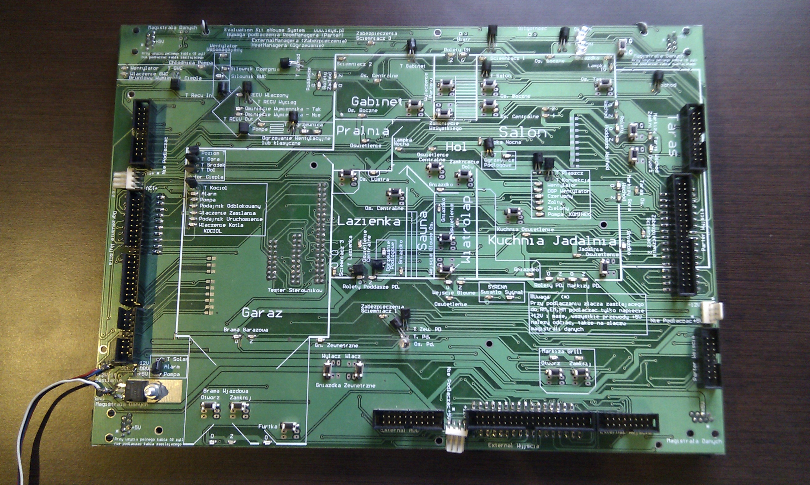
Smart House eHouse Demo – A full image
- Connector on the left side of the module are designed for HeatManager
- Connectors on the right side of the module are designed for RoomManager
- Connector on the bottom of the module for connection of ExternalManager or CommManager outputs
- All RS-485 bus connectors are shorted together internally, and you can use any RJ-45 socket
- All the connectors for the power bus drivers ( 4pin ) are analogous to each other tight and it does not matter which slot you use
Demo module should be fully connected to the tested drivers before turning on the power supply as follows:
Power Connection Home Automation Demo
Power supply connection ( without using a voltage to the module) + 12V , 0 into an outlet 4 pin PC computer power supply, the best computer on which you installed the software. Otherwise, provide a common proper grounding of all components.
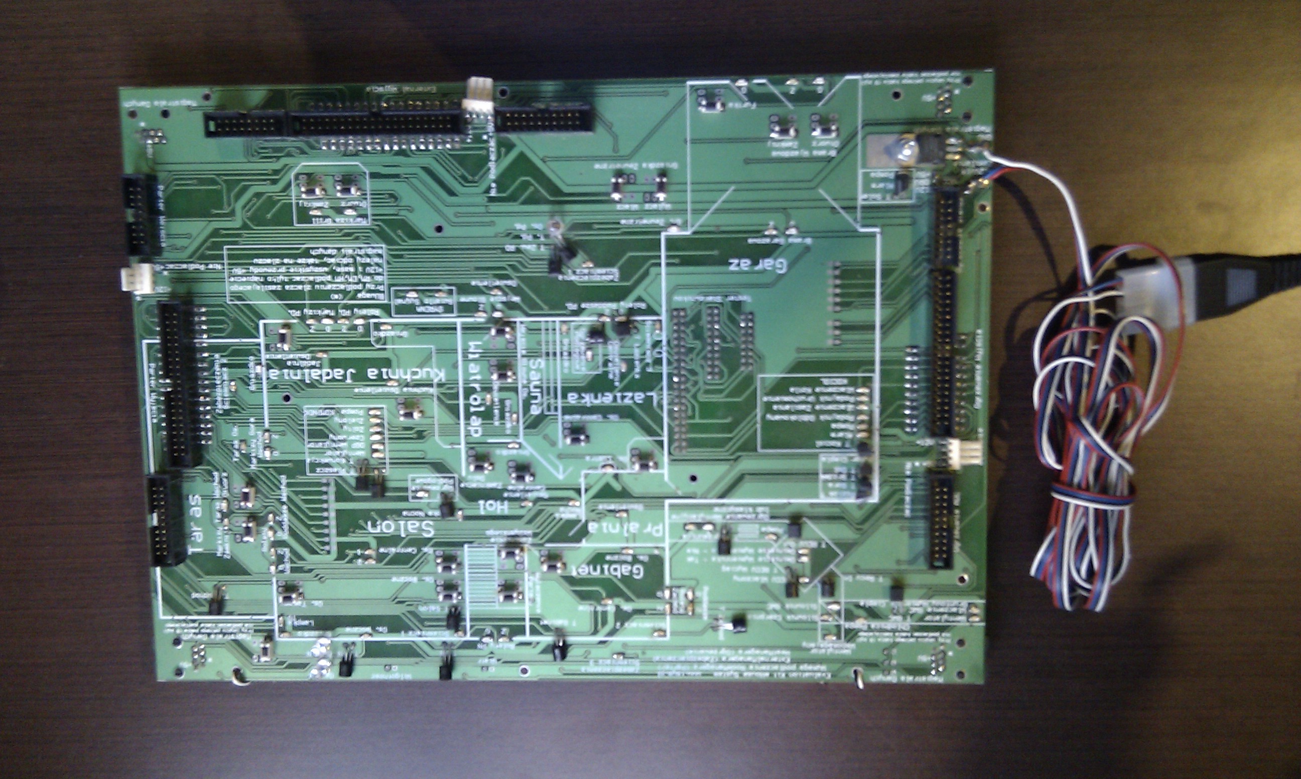
Power Connection Installation Demo eHouse smart home Full Screen
Connecting the RS-232 to RS-485 converter to demo module of eHouse smart home.
The converter is connected to any RJ-45 located on the module demo with full UTP cable-8 wires without cutting off because it is powered from eHouse data bus (we use the standard order of wires discussed in the installation documentation. The cable is clamped 1:1 without interlaces .
eHouse Smart Home – design DIY
Smart House eHouse – User self- installation
eHouse Smart House wiring connection details
In the case of the image module is connected to the notebook by adapter RS-232 to USB.

Connection to a PC Installation Demo of eHouse smart home Full Screen
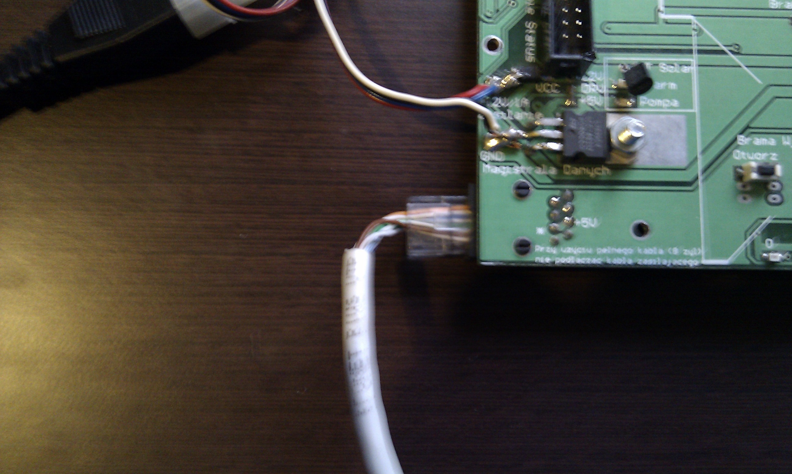
Connection to a PC Installation Demo of eHouse smart home Full Screen
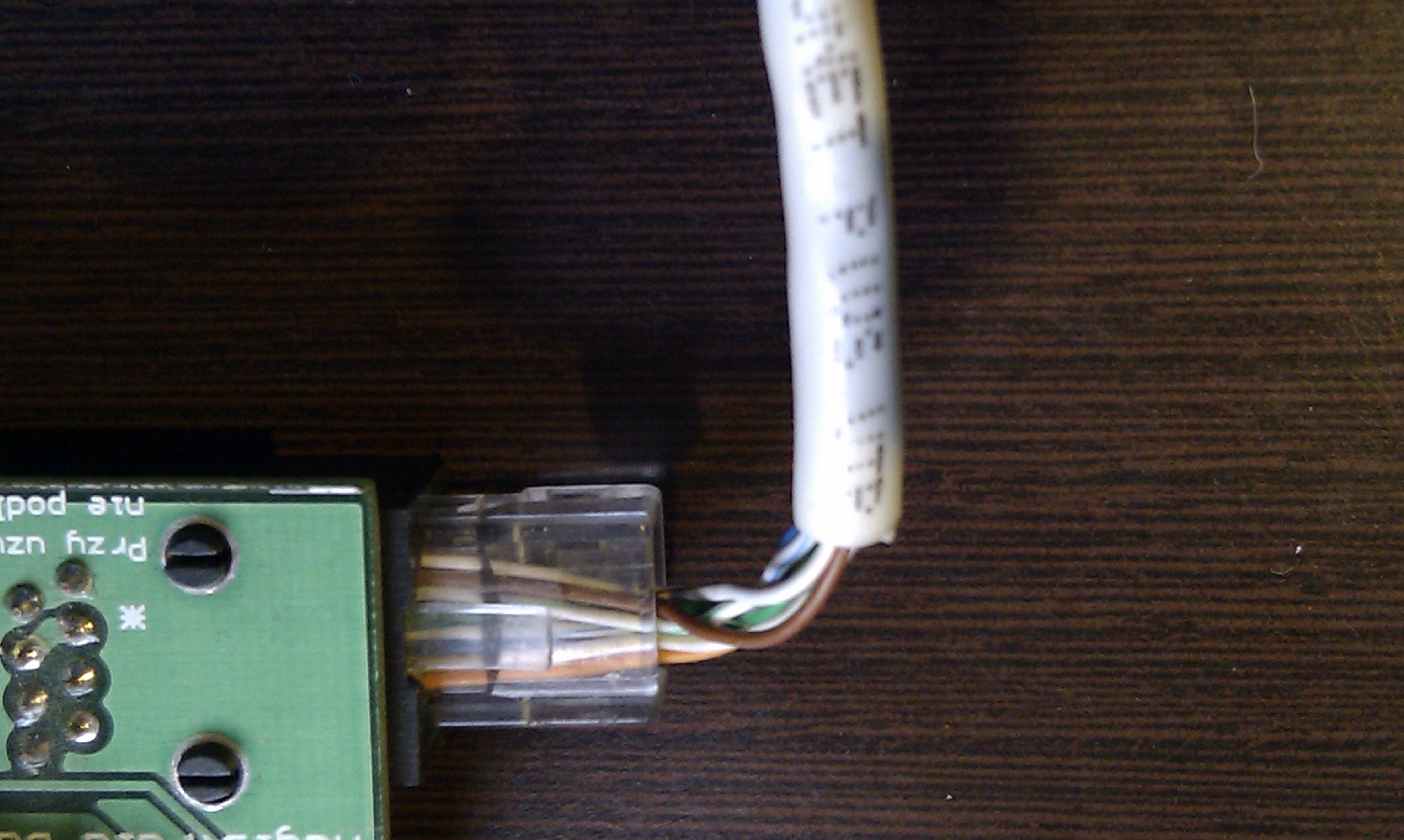
Connection to a PC Installation Demo of eHouse smart home Full Screen
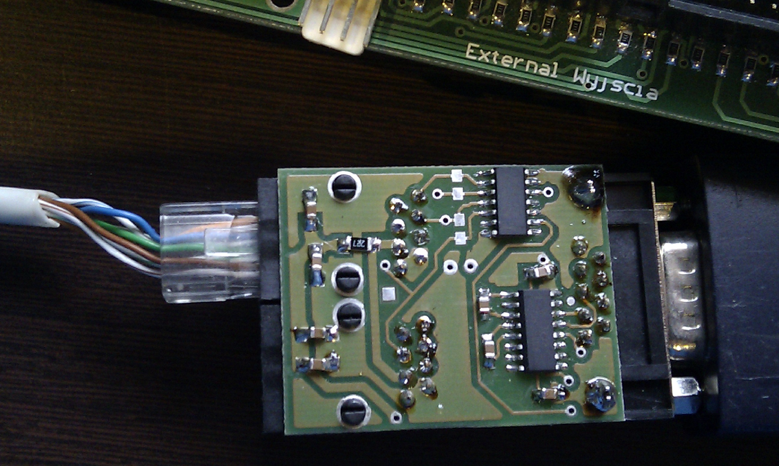
Connection to a PC Installation Demo of eHouse smart home Full Screen
Connecting the digital outputs and dimmers RoomManager flat IDC Tape – 40 ( 40pin – as for the IDE hard drive ) .
flat cable is clamped1: 1 without interlaces . For cable must have Crimping IDC .
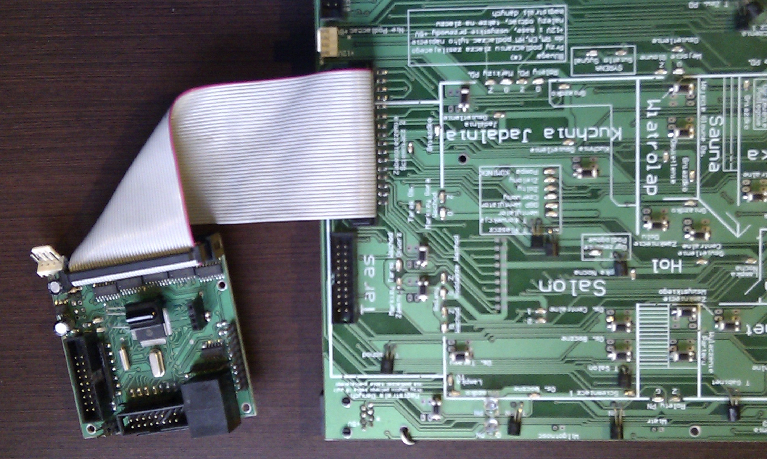
Connecting RoomManager the Installation Demo of eHouse smart home Full Screen
Connecting the analog inputs ( measurement ) RoomManager flat IDC Tape – 20 ( 20pin ) .
Flat cable is clamped 1:1 without interlaces .
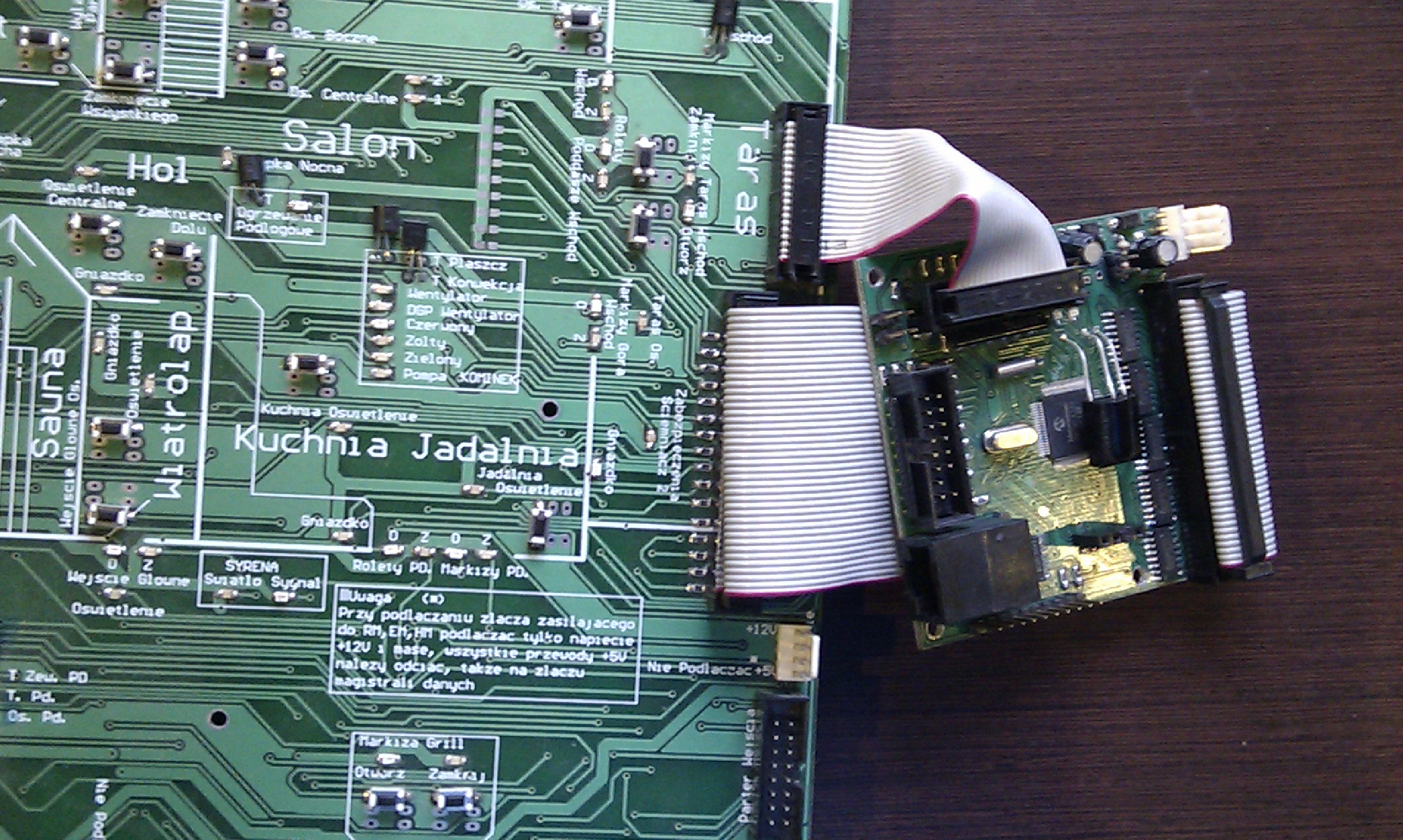
Connecting RoomManager the Installation Demo of eHouse smart home Full Screen
Connecting the digital inputs RoomManager flat IDC-16 Tape ( 16pin ) .
Flat cable is clamped 1:1 without interlaces .
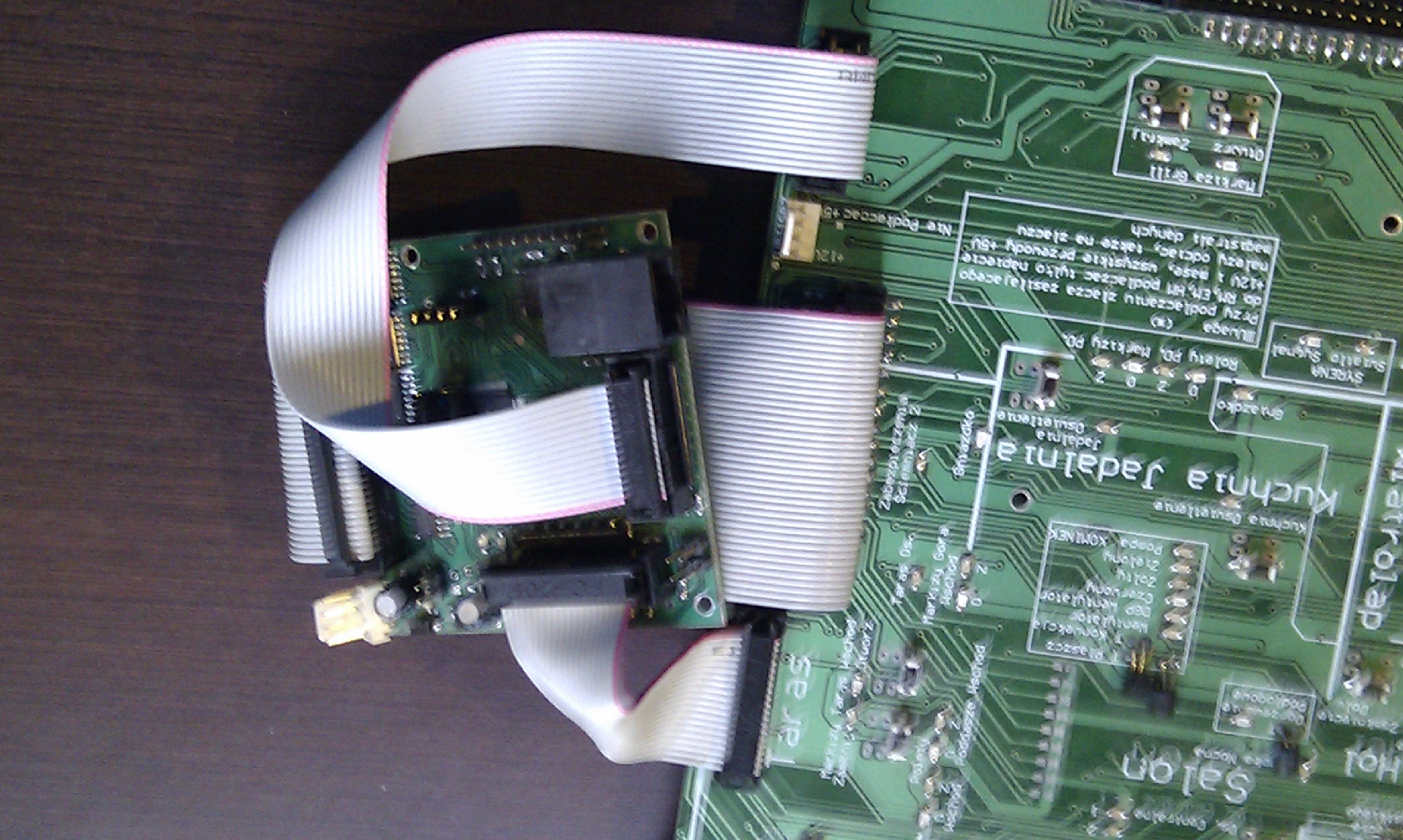
Connecting RoomManager the Installation Demo of eHouse smart home Full Screen
Connecting the data bus to RoomManager UTP-8 cable and clenched RJ-45 connectors ( F )
1 is clamped cable 1 without interlaces . In the case of power RoomManager power bus must be cut 2 wires ( white-green and green) according to the standard color eHouse bus .
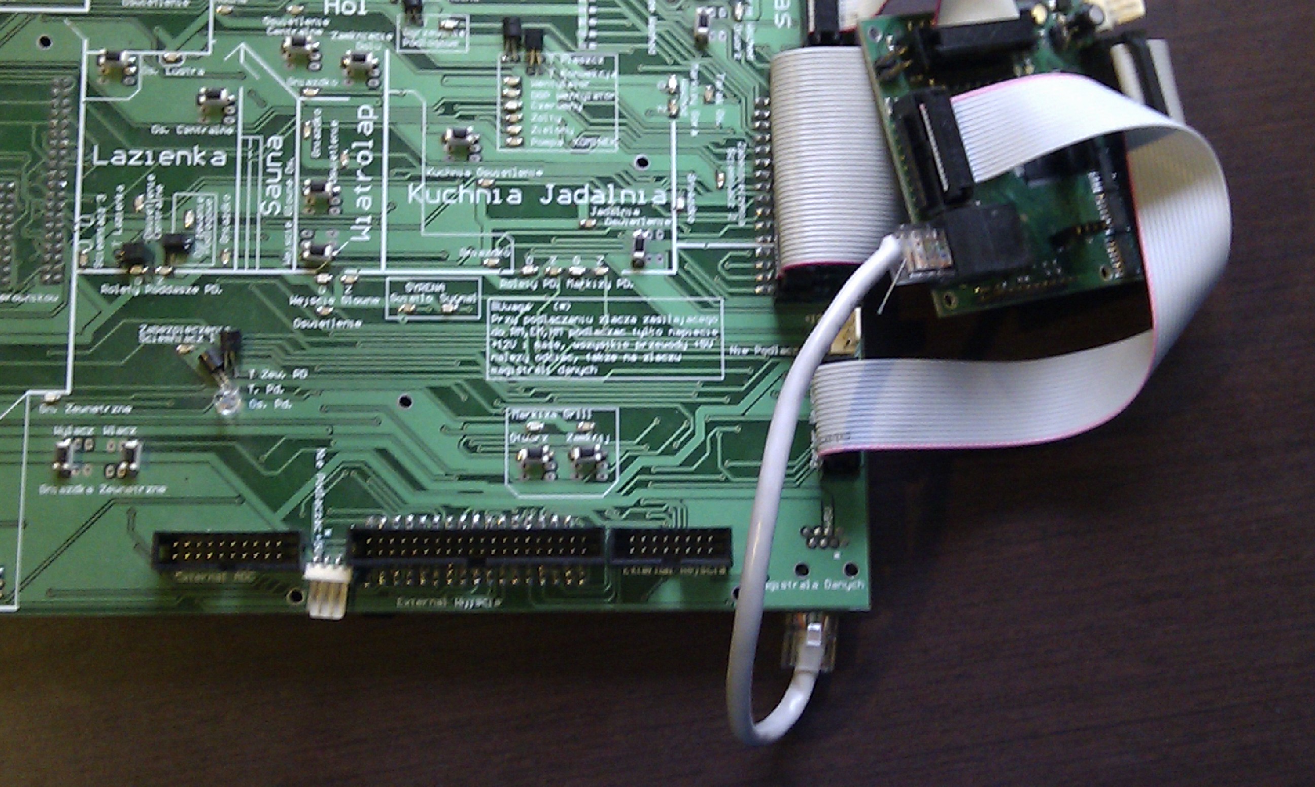
Connecting RoomManager the Installation Demo of eHouse smart home Full Screen
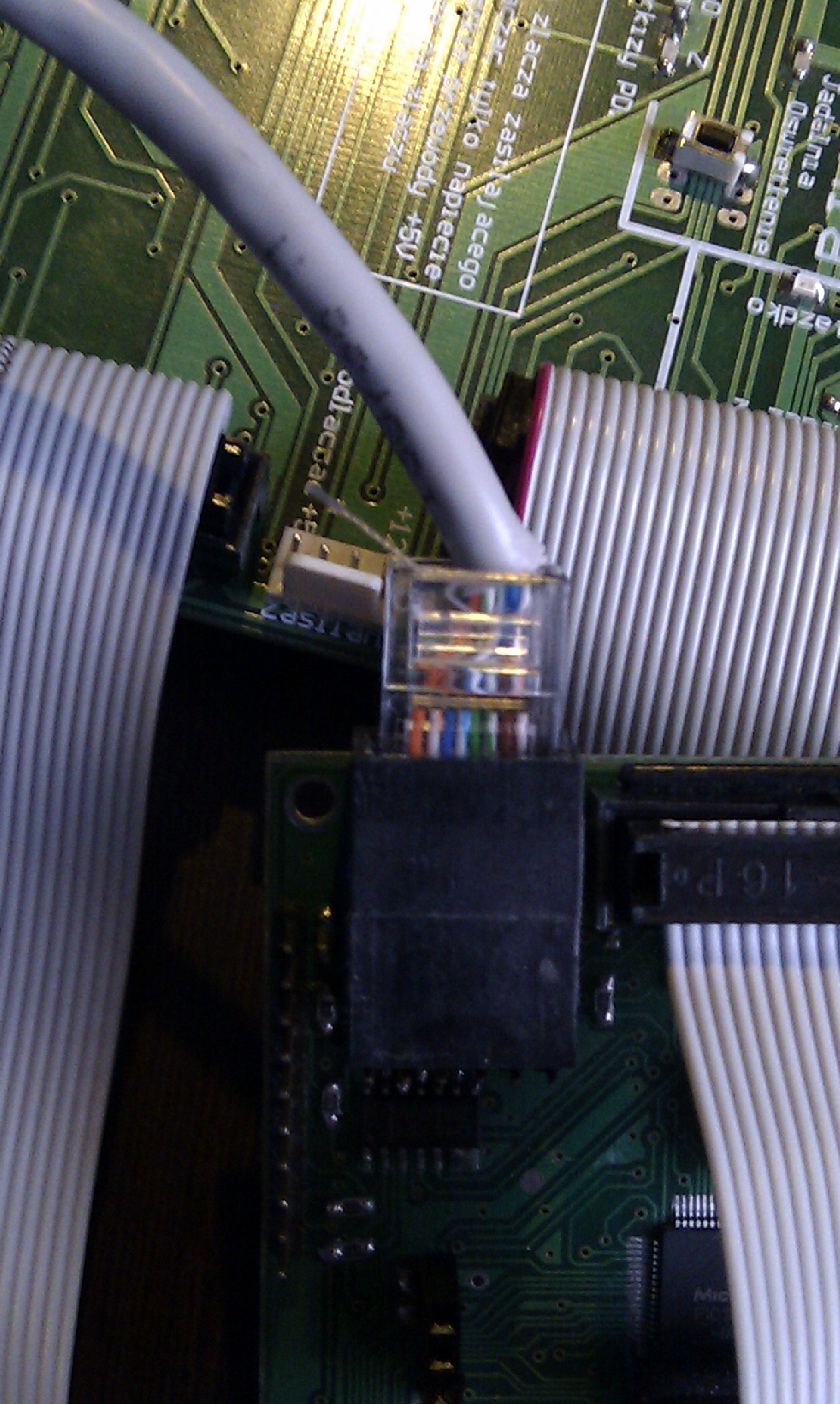
Connecting RoomManager the Installation Demo of eHouse smart home Full Screen
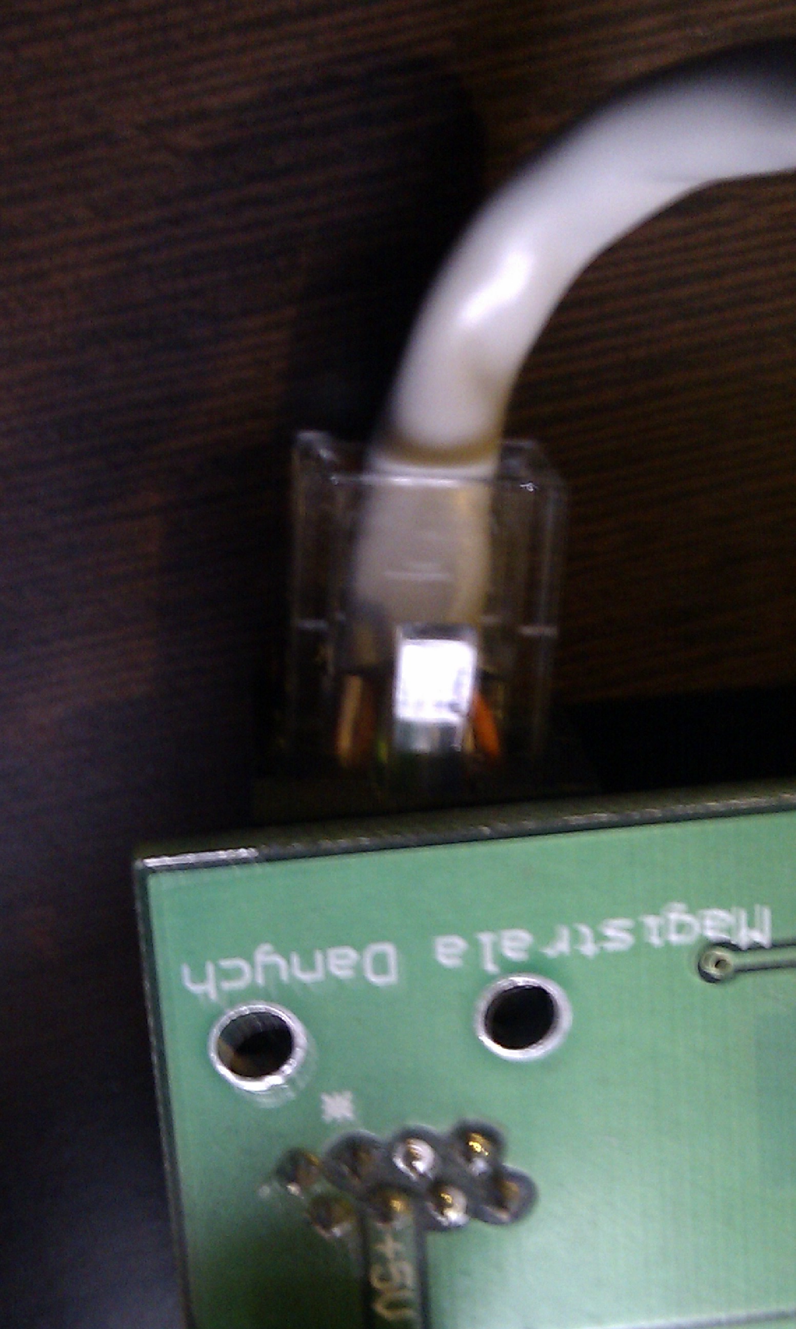
Connecting RoomManager the Installation Demo of eHouse smart home Full Screen
Connecting RoomManager the power bus. RoomManager supplies only a single voltage of 12V ( 4pin connector ).
In the case of power RoomManager the 12V power bus must be cut off supply lines (5V bus line data , see above ) .
Wire 5V on the data bus must also be disconnected . All controllers have built-in stabilizers eHouse voltage to the value required by the module .
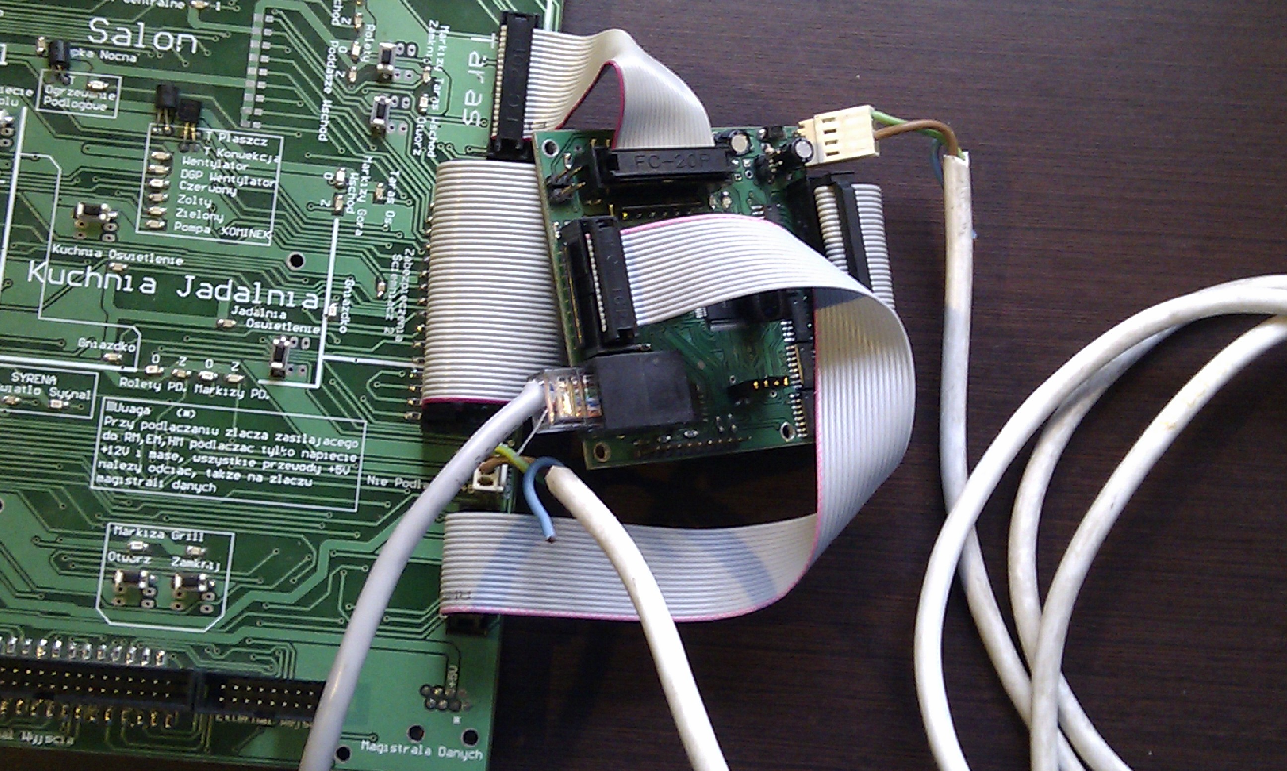
Connecting RoomManager the Installation Demo of eHouse smart home Full Screen
After several sure that all cables are connected properly adjusted and turn on the power supply:
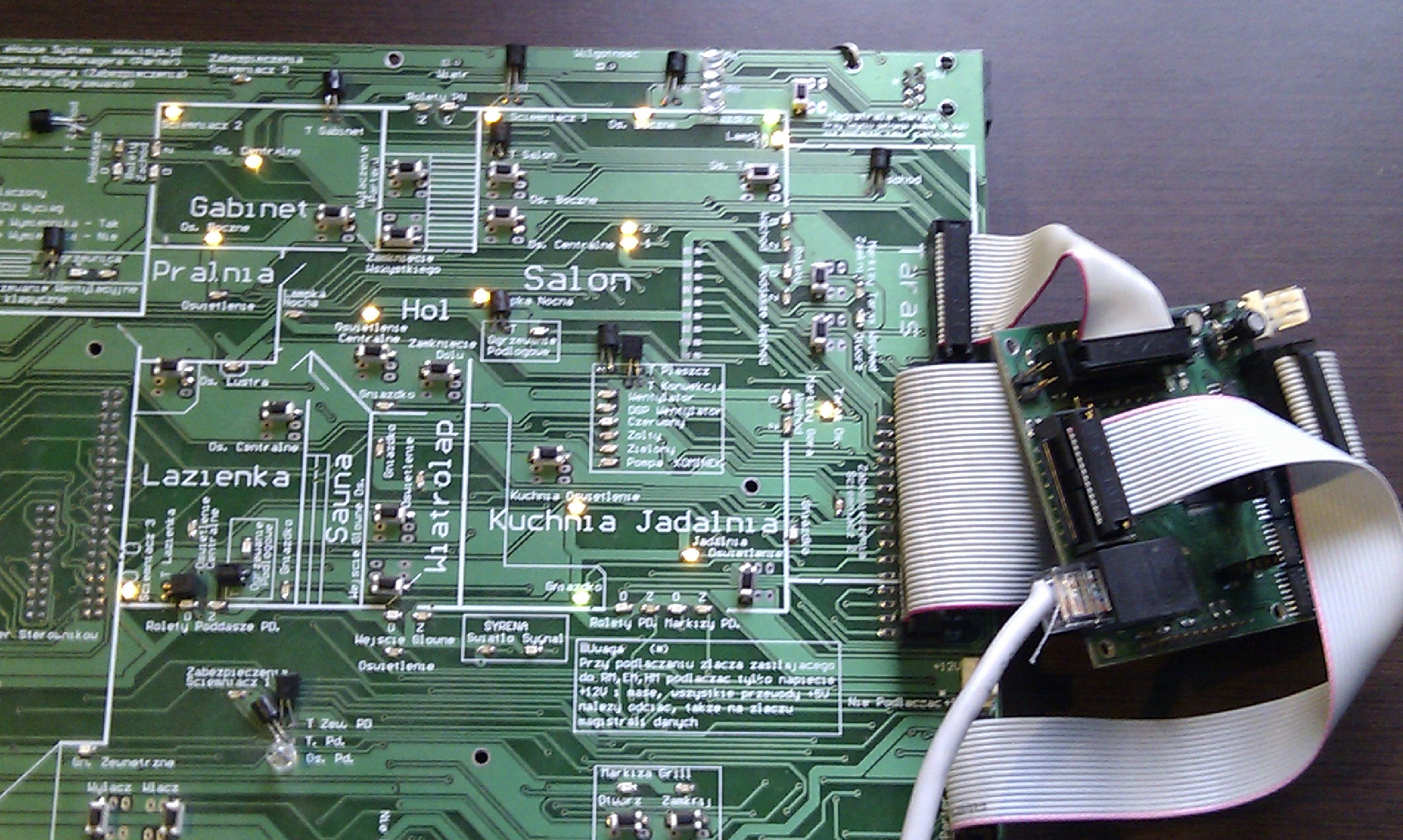
Connecting RoomManager the Installation Demo of eHouse smart home Full Screen
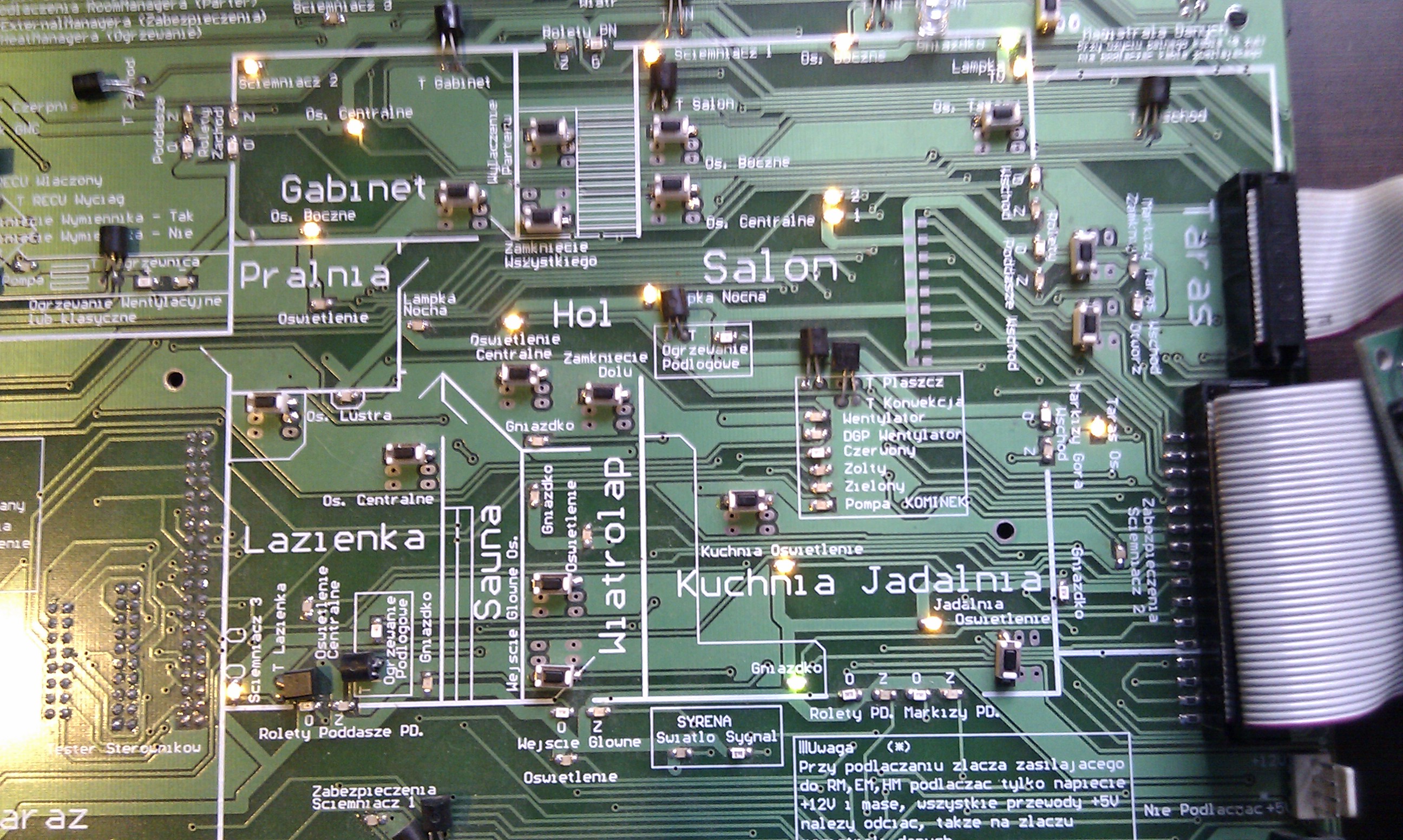
Connecting RoomManager the Installation Demo of eHouse smart home Full Screen
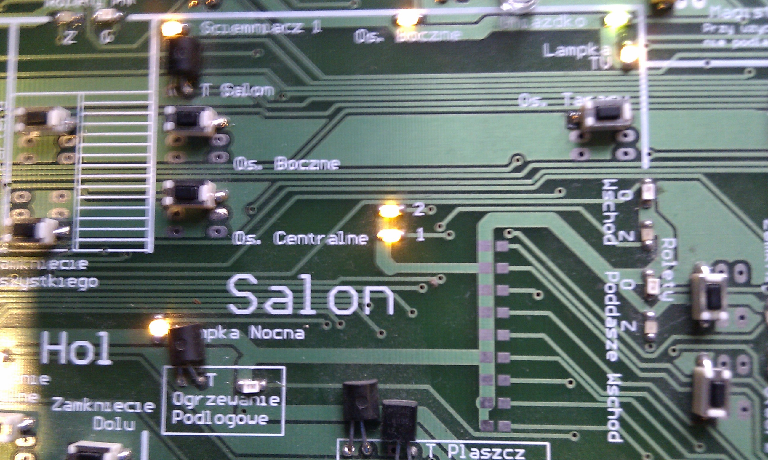
Connecting RoomManager the Installation Demo of eHouse smart home Full Screen
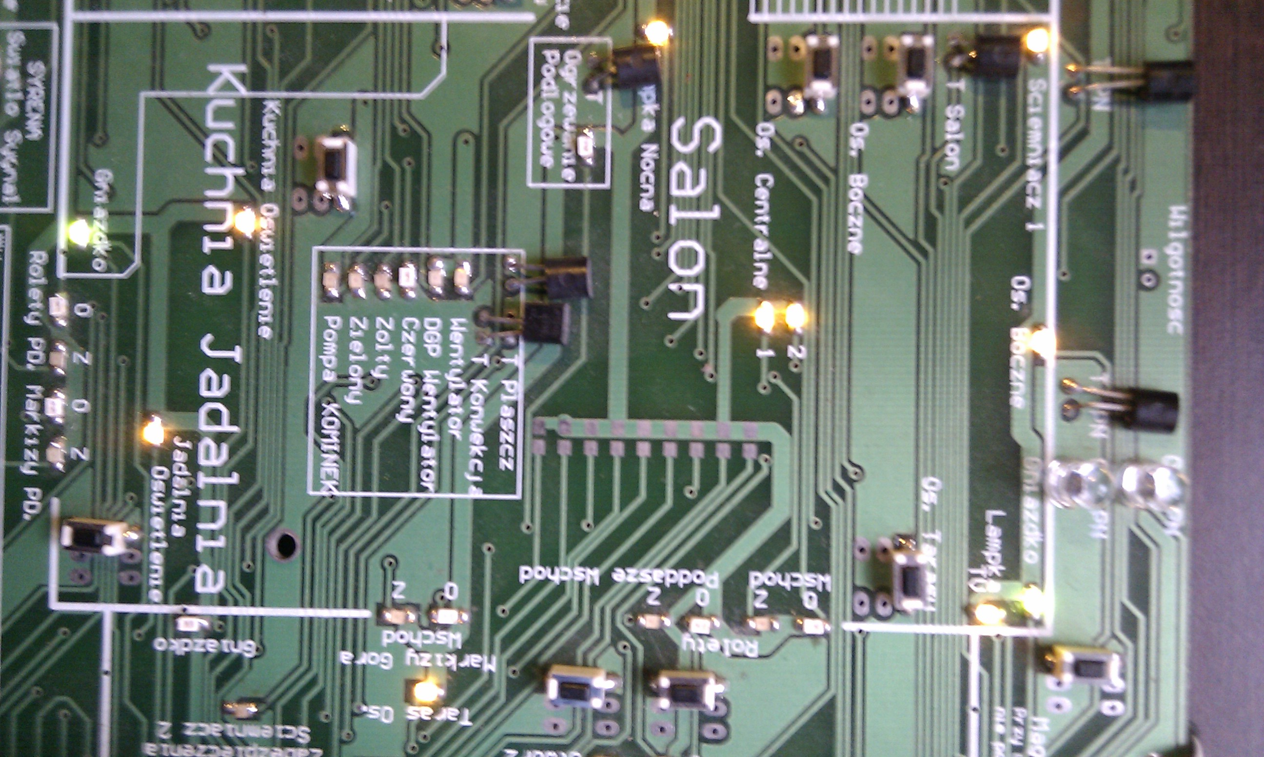
Connecting RoomManager the Installation Demo of eHouse smart home Full Screen
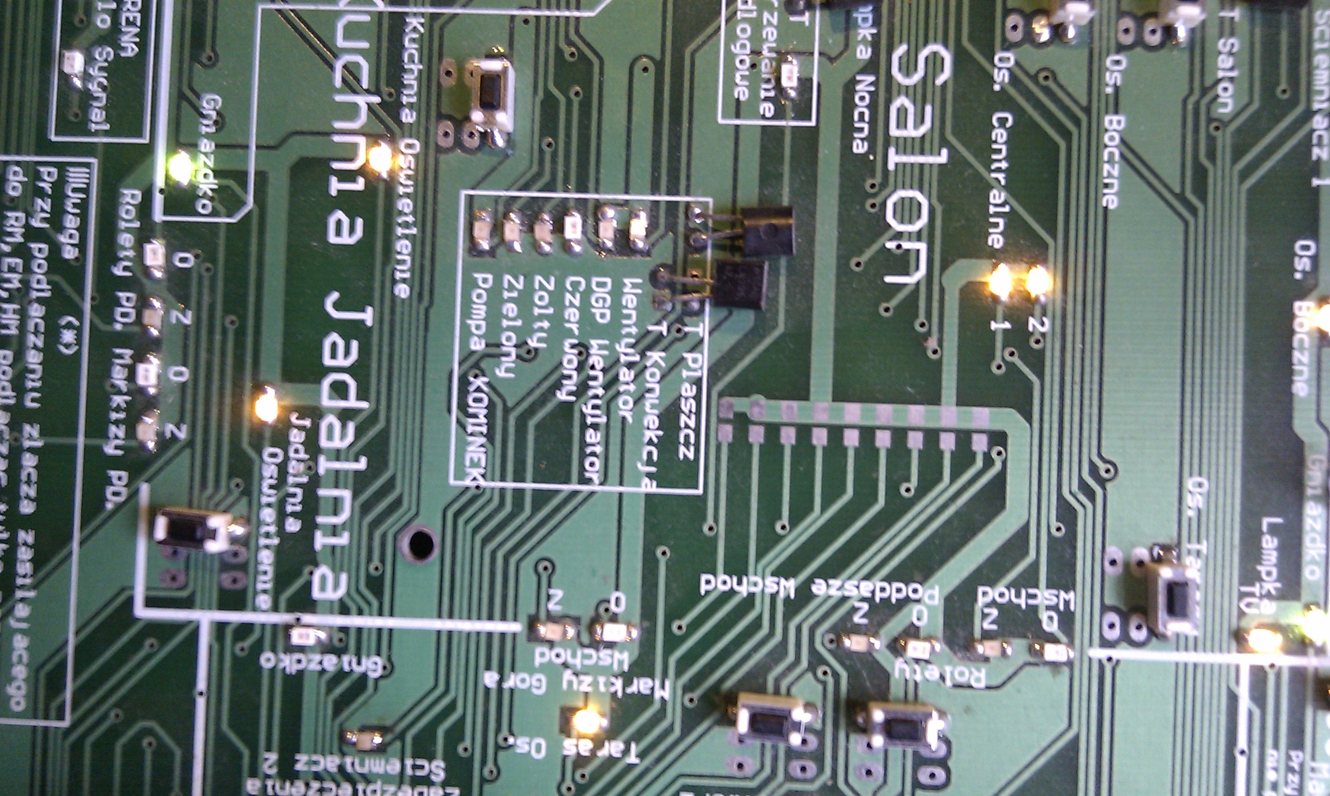
Connecting RoomManager the Installation Demo of eHouse smart home Full Screen
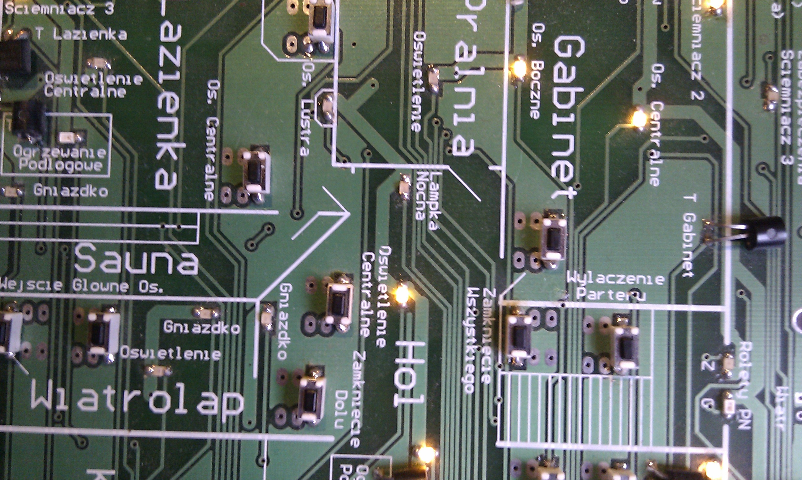
Connecting RoomManager the Installation Demo of eHouse smart home Full Screen
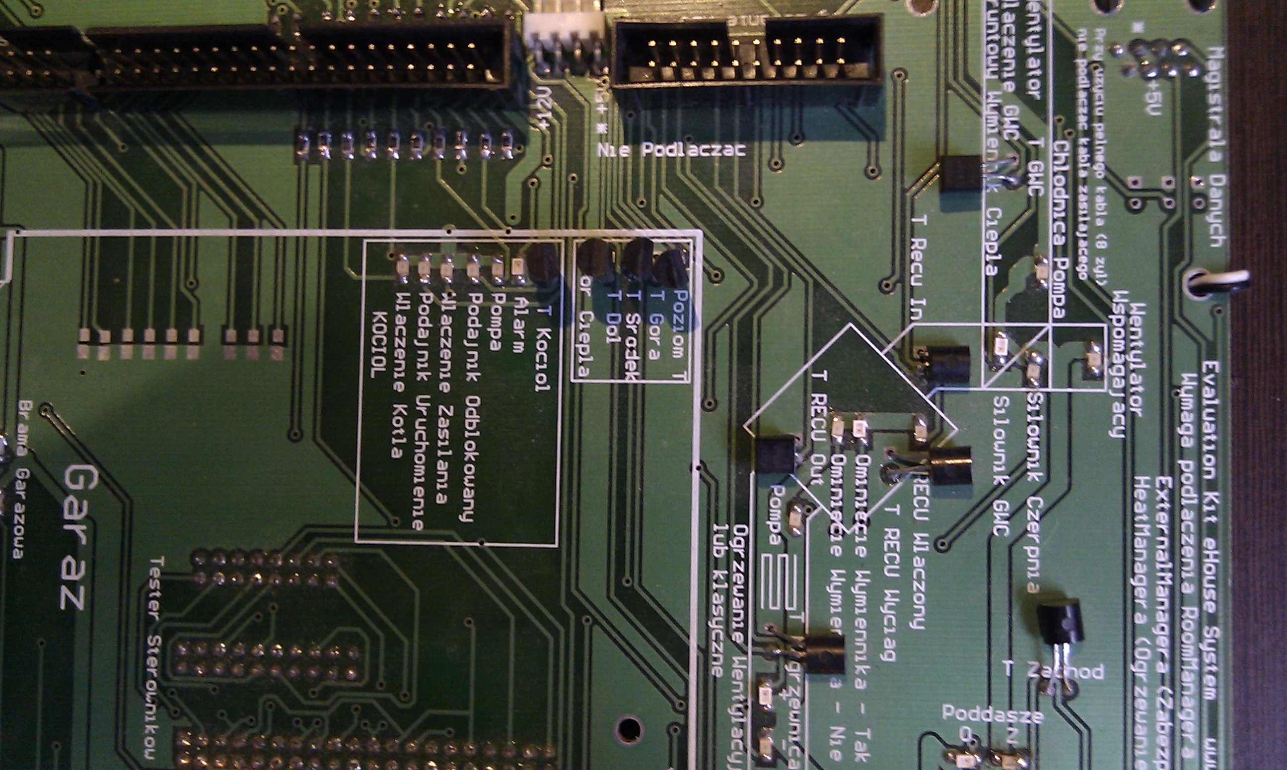
Connecting RoomManager the Installation Demo of eHouse smart home Full Screen
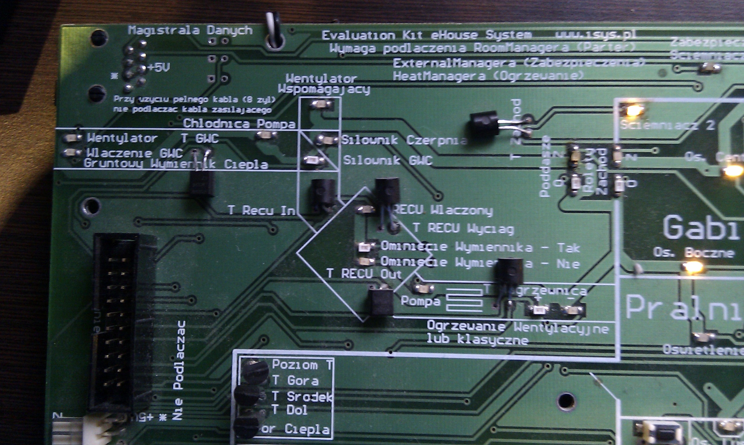
Connecting RoomManager the Installation Demo of eHouse smart home Full Screen

Connecting RoomManager the Installation Demo of eHouse smart home Full Screen
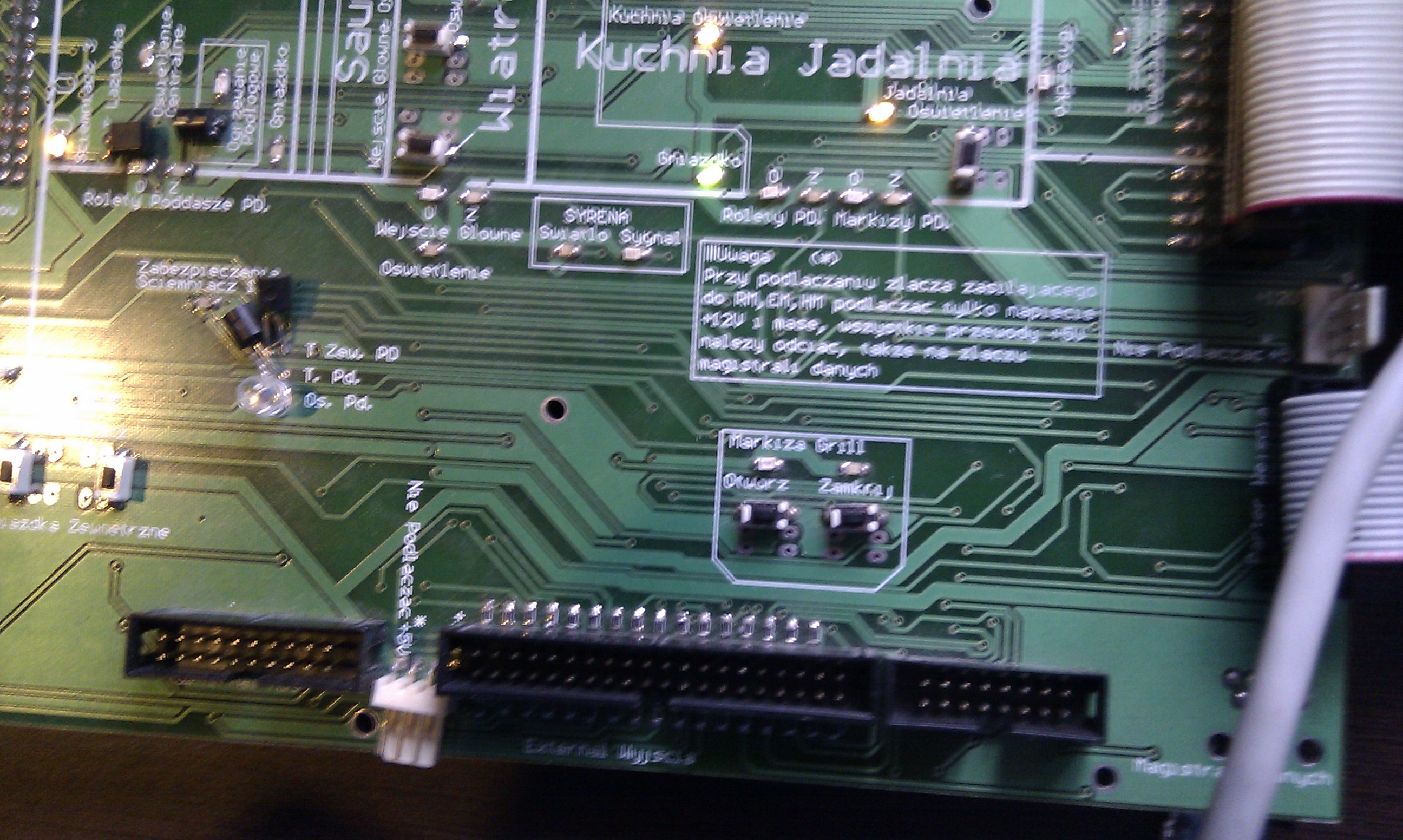
Connecting RoomManager the Installation Demo of eHouse smart home Full Screen
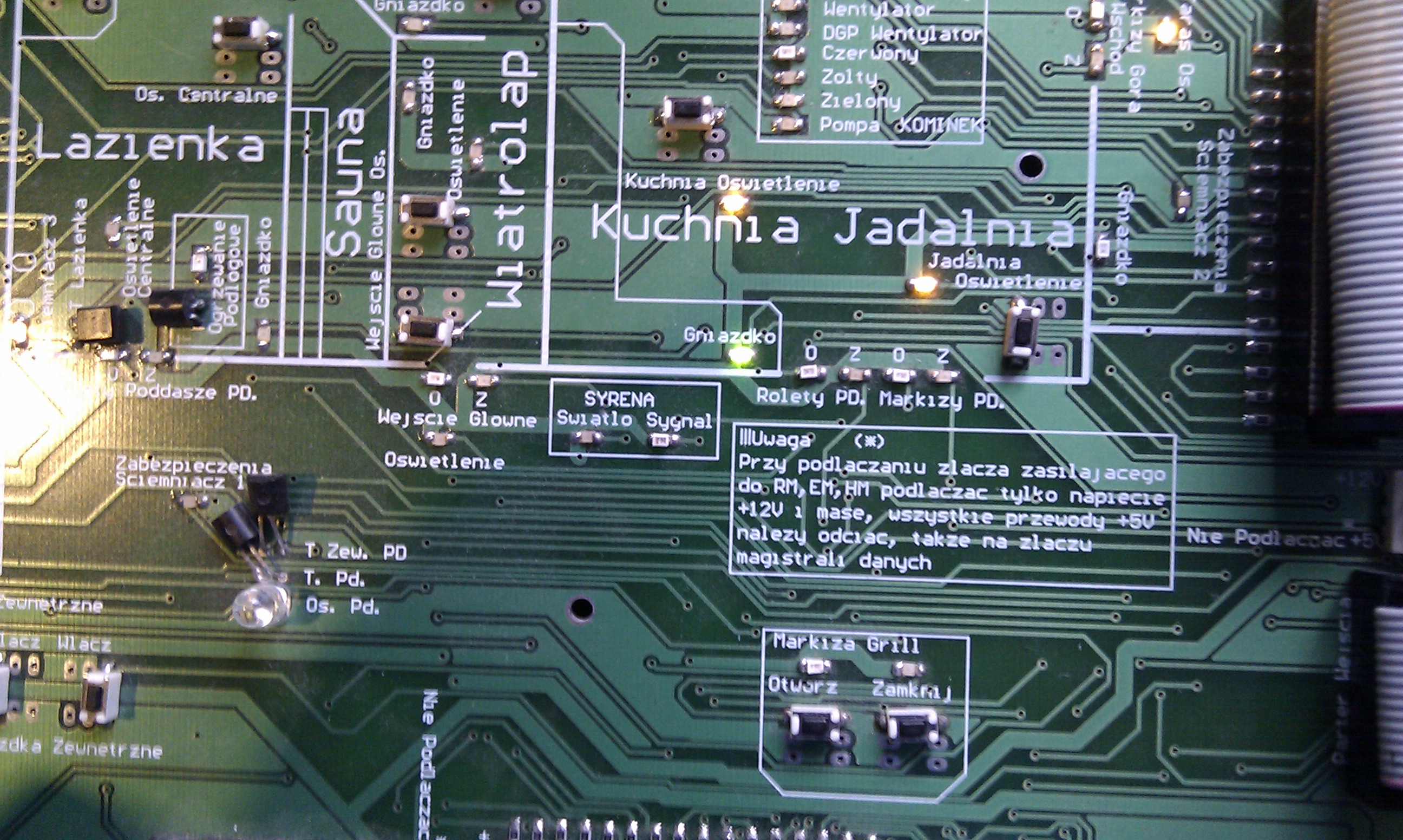
Connecting RoomManager the Installation Demo of eHouse smart home Full Screen
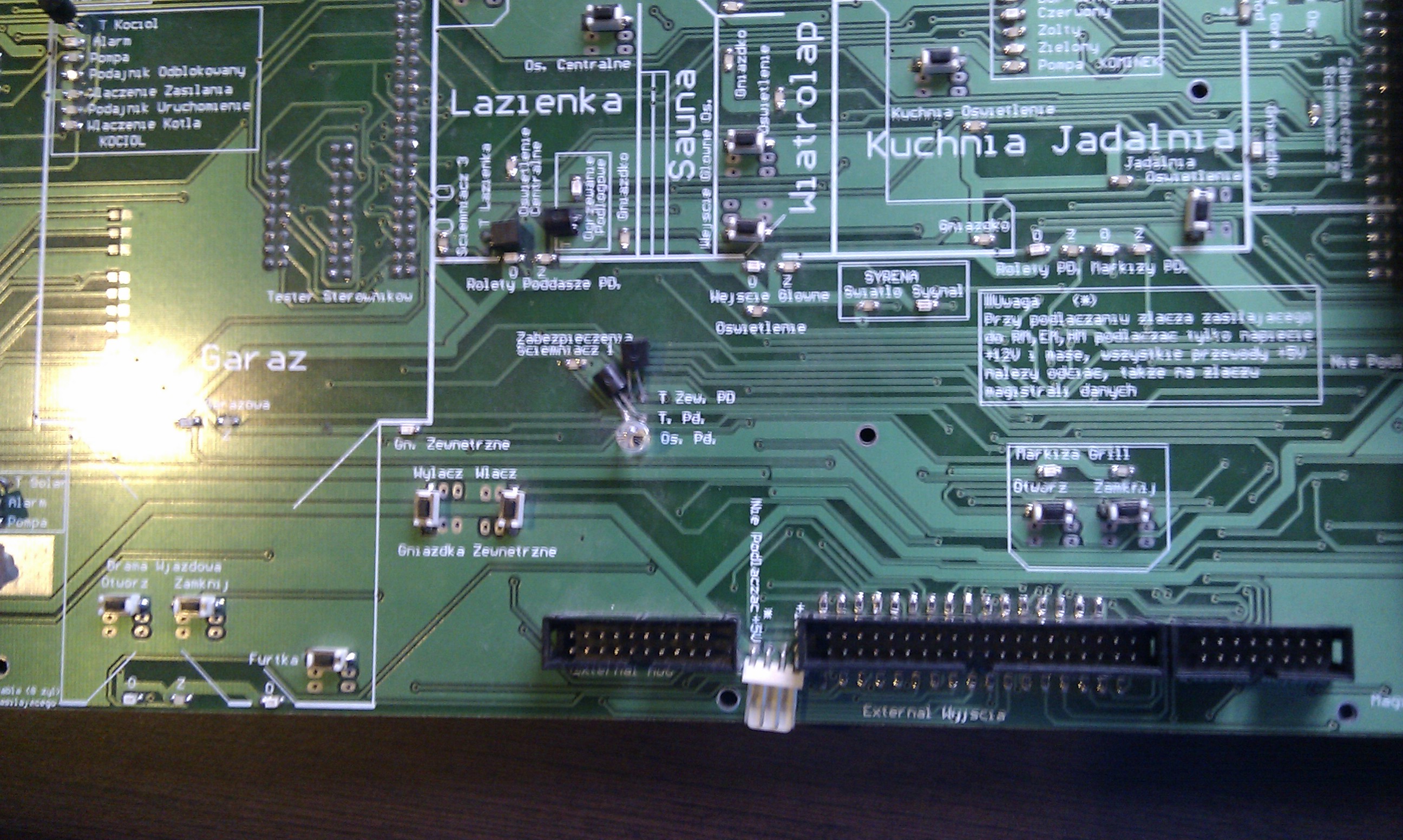
Connecting RoomManager the Installation Demo of eHouse smart home Full Screen
Other eHouse 1 home automation system controllers are connected in the same way.
After power module demo , check the communication with the PC serial port COMx to which we connected the system by typing in configuration files “com.cfg” and “SAMPLES/com.cfg” Number port .
In case of problems , check the communication with the application HYPERTERMINAL checking the serial port by setting the transmission parameters
speed = 115200
1bit stop
no flow control
parity (E ) Even
Controllers will send restart confirmation after power reset signal, which is visible in the terminal application .
Reset is repeated every few minutes in the absence of communication with the eHouse software .