eHouse4CAN Intelligent Home, Apartment controllers
eHouse for CAN (Controller Area Network) Smart Home system is dedicated to person who do not need a large installation of building automation controllers based on RoomManagers , created a version of eHouse working on the CAN serial bus.
Controllers are much smaller than RoomManager, EthernetRoomManager, CommManager, HeatManager and can be located directly in electric socket cans. Additionally it implements build in relays.
In spite of this, you can control any external devices combining the functionality of all eHouse1 and Ethernet eHouse controllers.
Intelligent controllers were originally designed for smaller installations while simplifying assembly process, which is particularly valuable in the case of self-assembly by the investor or local installers installing building automation system for the first time.
Drivers are small and fit in a standard electrical cans :
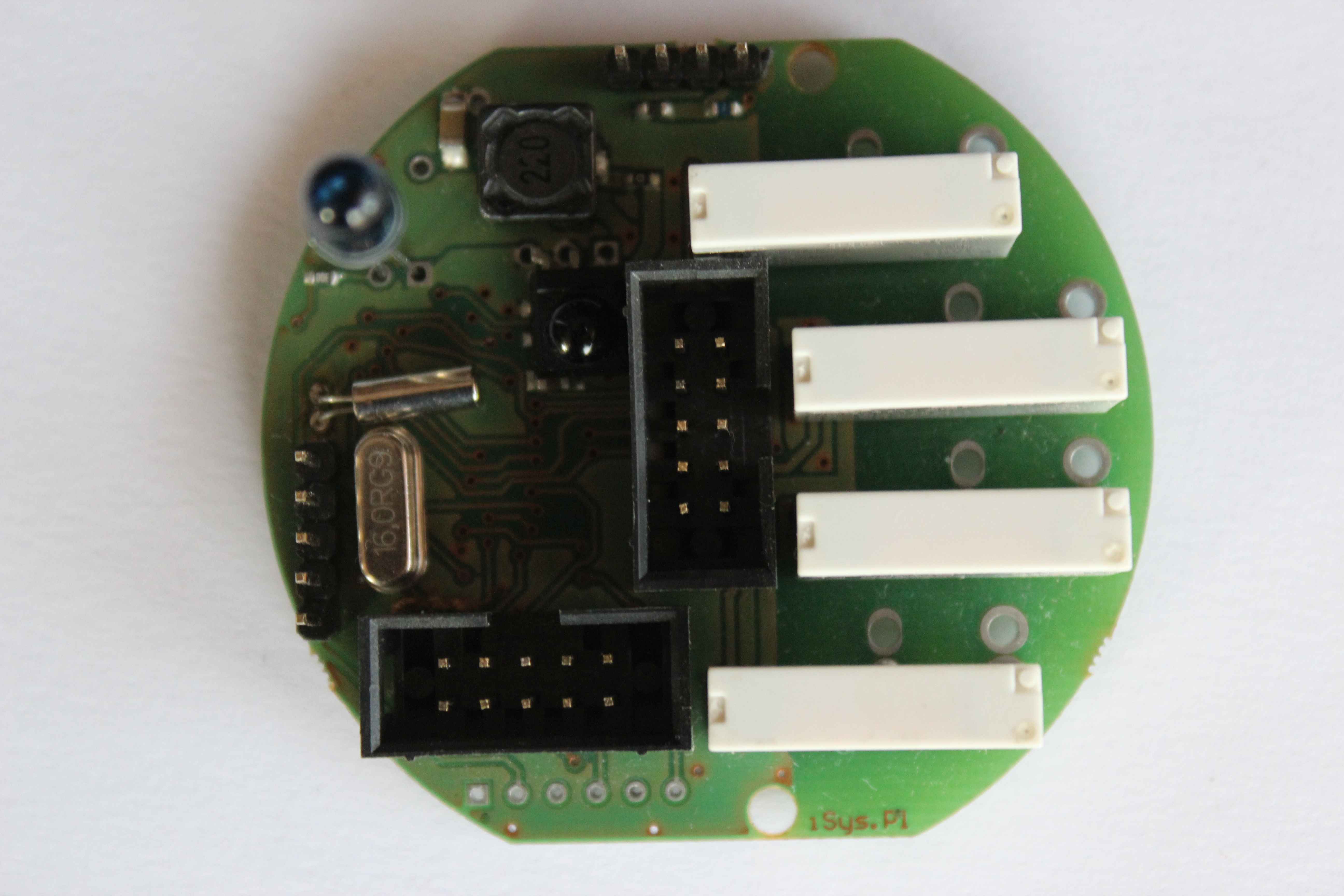
Are linked together in a network using a UTP cable – 8 ( twisted pair cable ) using only 4 lines including power supply.
Others can be used as a spare or connected in parallel to the power supply to reduce the voltage drop on long wires.
In small installations, drivers can be combined into a star ( wires meet in one point) and also can use IDC-10 cable instead UTP.
In large installation it is recommended to connect the serial drivers.
CAN bus with the power supply located on the 4-pin connector:
pin no. 1 has a square section and the solder is located on the mass ( 0V) in the vicinity of the plane of the path of a large board
- 1 – GND , Ground , 0V ( UTP cable – 8 color brown and white – brown)
- 2 – CAN + – data bus line inverting ( white – blue)
- 3 – CAN – – CAN data bus line Inversion ( blue)
- 4 – +VCC (+9..+25V) – voltage POSITIVE power to the controller (green and white – green)
CAN bus with the power supply located on the 6-pin connector IDC-6:
pin no. 1 has a square section and the solder is located on the mass ( 0V) in the vicinity of the plane of the path of a large board
- 1 – GND , Ground , 0V ( UTP cable – 8 color brown and white – brown)
- 2 – GND , Ground , 0V ( UTP cable – 8 color brown and white – brown)
- 3 – CAN + – data bus line inverting ( white – blue)
- 4 – CAN – – CAN data bus line Inversion ( blue)
- 5 – +VCC (+9..+25V) – voltage POSITIVE power to the controller (green and white – green)
- 6 – +VCC (+9..+25V) – voltage POSITIVE power to the controller (green and white – green)
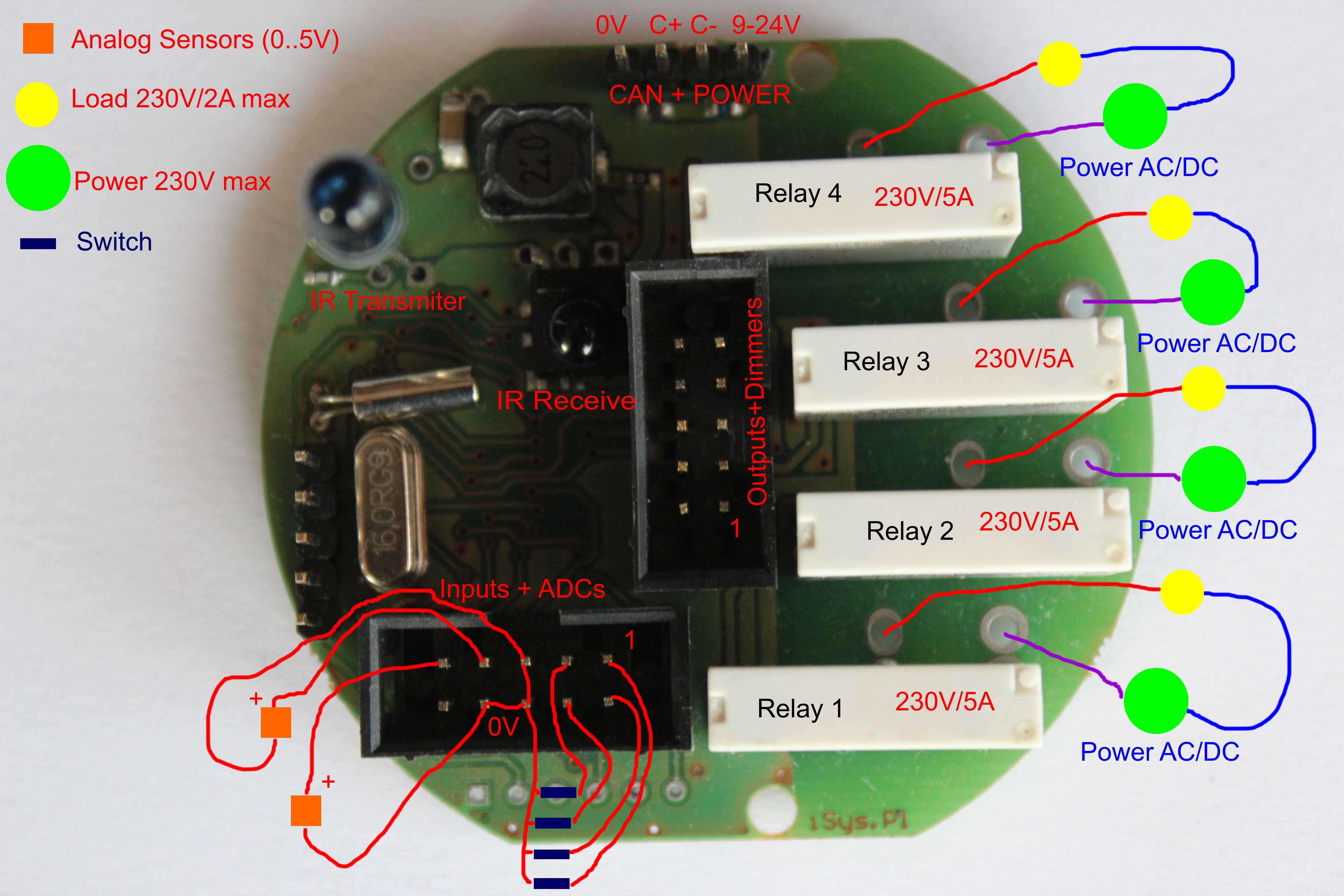
10 pin connector on the side of the plate ( digital and analog inputs )
- 1 . Digital input 1 (for switches)
- 2 . Digital input 2 (for switches)
- 3 . Digital input 3 (for switches)
- 4 . Digital input 4 (for switches)
- 5 . GND , 0V , Ground ( common for switches )
- 6 . GND , 0V , Ground ( common for switches / sensors)
- 7 . Measuring input 1 ( analog sensors 0 – 5V )
- 8 . GND , 0V , Ground ( common for switches / sensors)
- 9 . Measuring input 1 ( analog sensors 0 – 5V )
- 10 . 5V VCC – voltage panels , back light switches , etc. for external LEDs
10 pin connector in the middle of the PCB ( output buffers {Digital Out} + dimmer PWM) DO NOT CONNECT IF RELAY soldered on the board
- 1 . Digital output 1 driver – directly connecting the relay
- 2 . Digital output 2 driver – directly connecting the relay
- 3 . Digital output 3 driver – directly connecting the relay
- 4 . Digital output 4 driver – directly connecting the relay
- 5 . dimmer 1 – the output of the CMOS processor
- 6 . dimmer 2 – the output of the CMOS processor
- 7 . dimmer 3 – the output of the CMOS processor
- 8 . dimmer 4 – the output of the CMOS processor
- 9 . VCCDRV – Power relays diodes
- 10 . GND , 0V , Ground
3-pin connector ( the IR receiver TSOP34136 soldered or external)
- 1 . IR receiver input
- 2 . GND , 0V , Ground
- 3 . VCC , + 5V power infrared receiver
2 pin connector ( IR transmitter – IR emitter diode )
- 1 . VCC , + 5V , Anode IR LEDs
- 2 . Output IR LED cathode driver
Drawing showing how to connect a single driver.