eHouse CAN intelligent apartment , Home Automation controller connection of inputs
Smart Home eHouse self-control connection eHouse4CAN – digital and analog inputs (switches and sensors).
This article describes (single board) ehouse CAN controller. For multi-board “eHouse CAN/RF” controller please refer most current post.
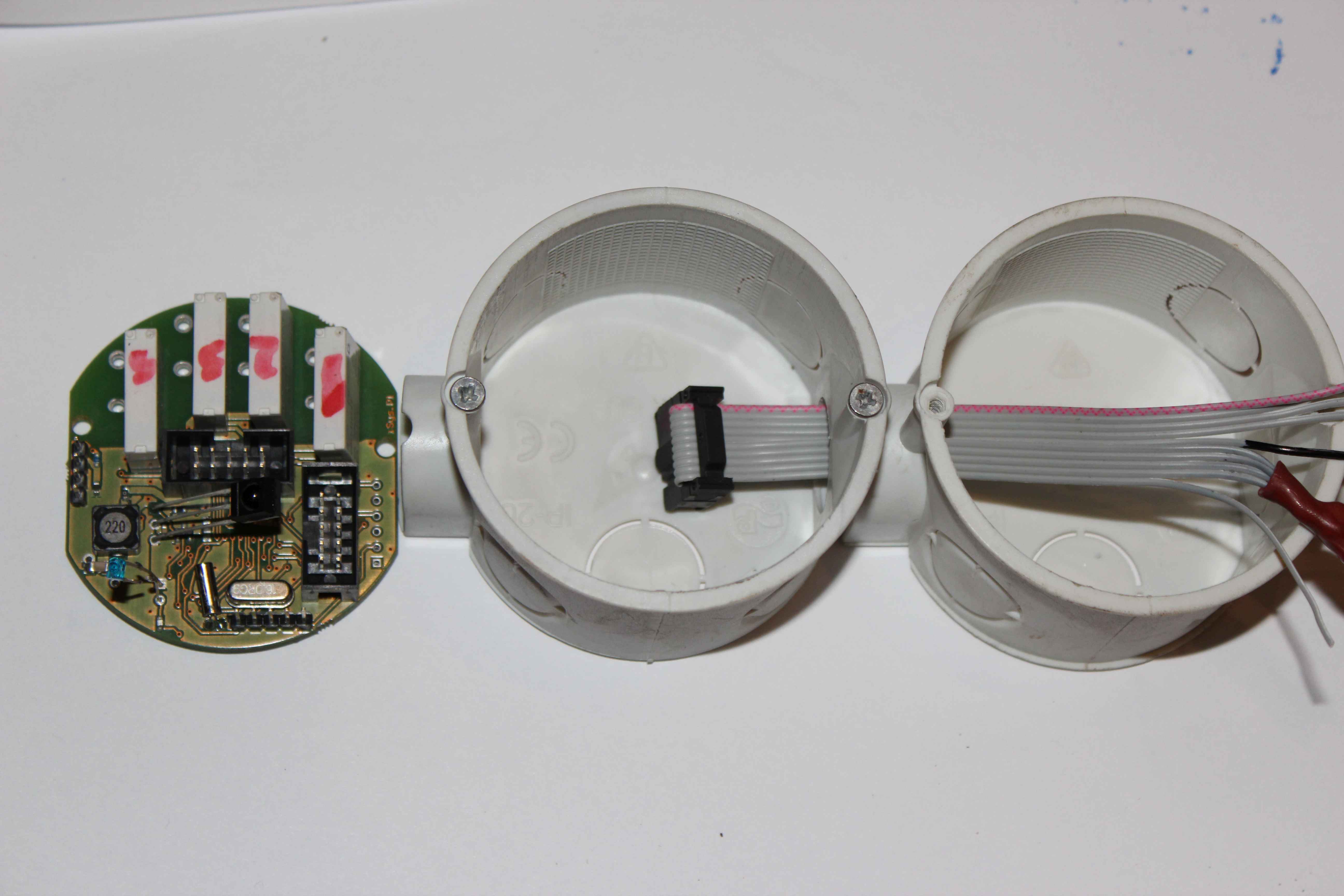
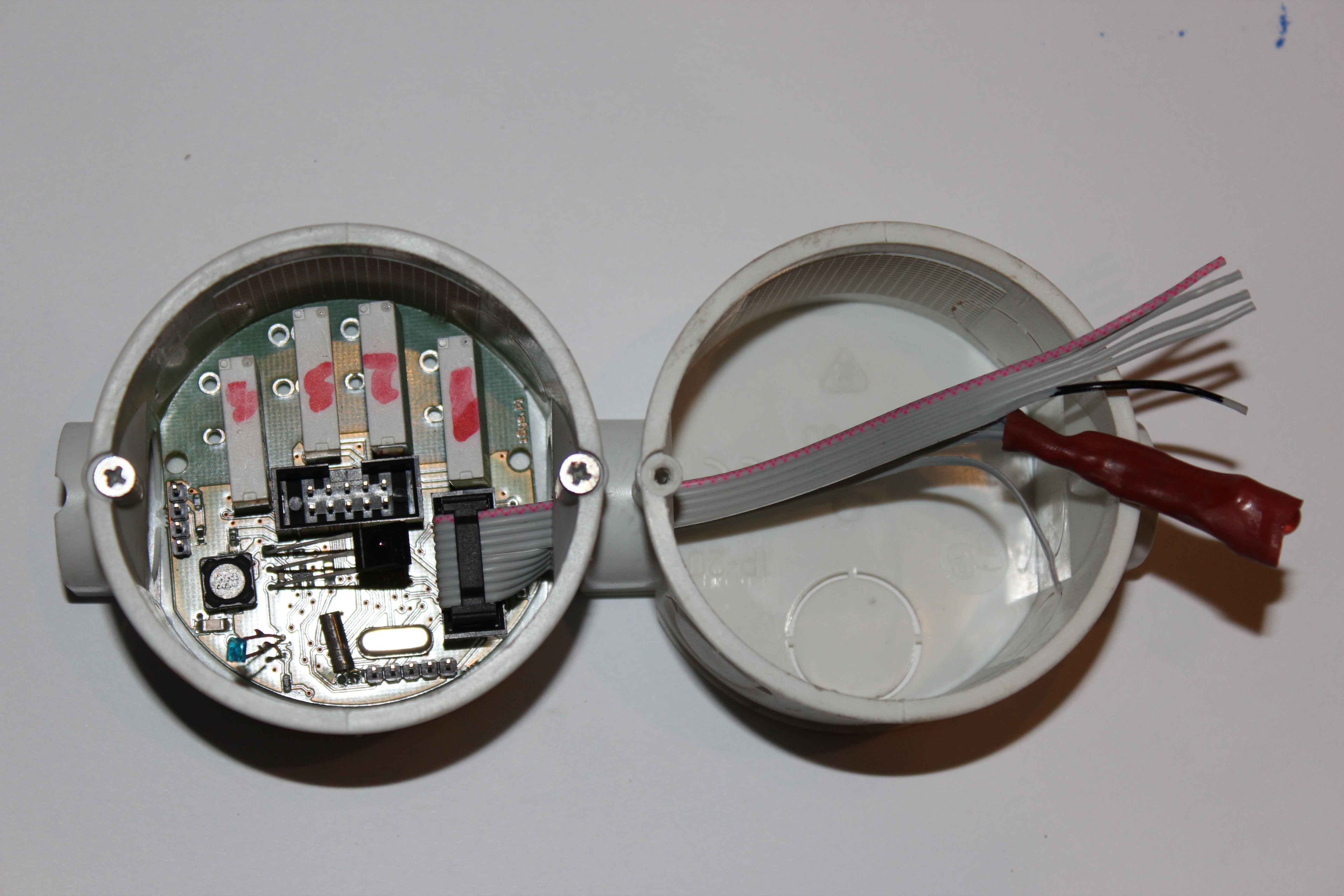
Drivers are mounted directly in the wall sockets (cans) directly. For convenience it is the best to use a deep can.
Pin description can be found at Smart Home eHouse CAN Lead .
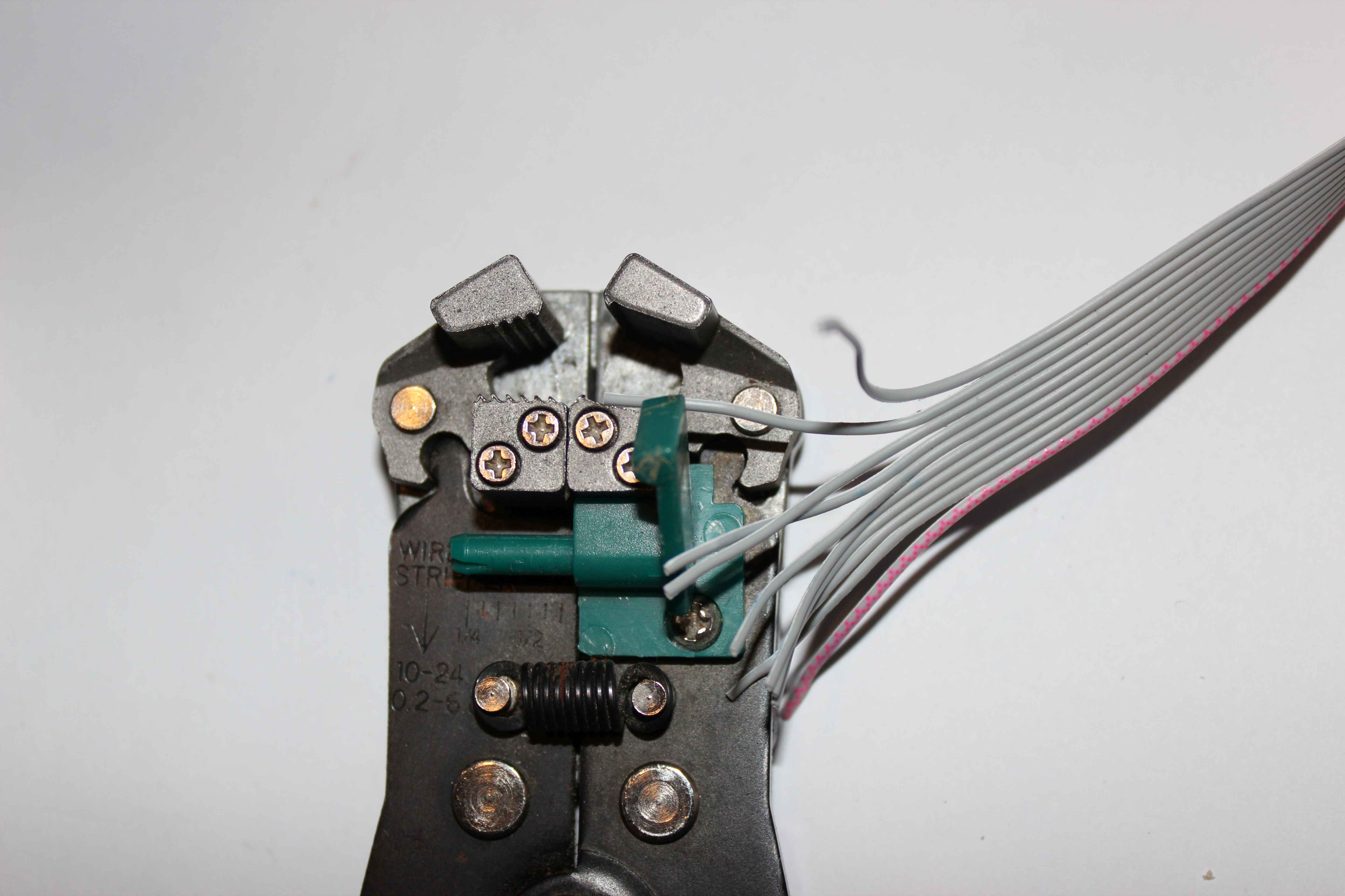
For installation it is necessary to have a tool for stripping and cutting wires, as in the picture.
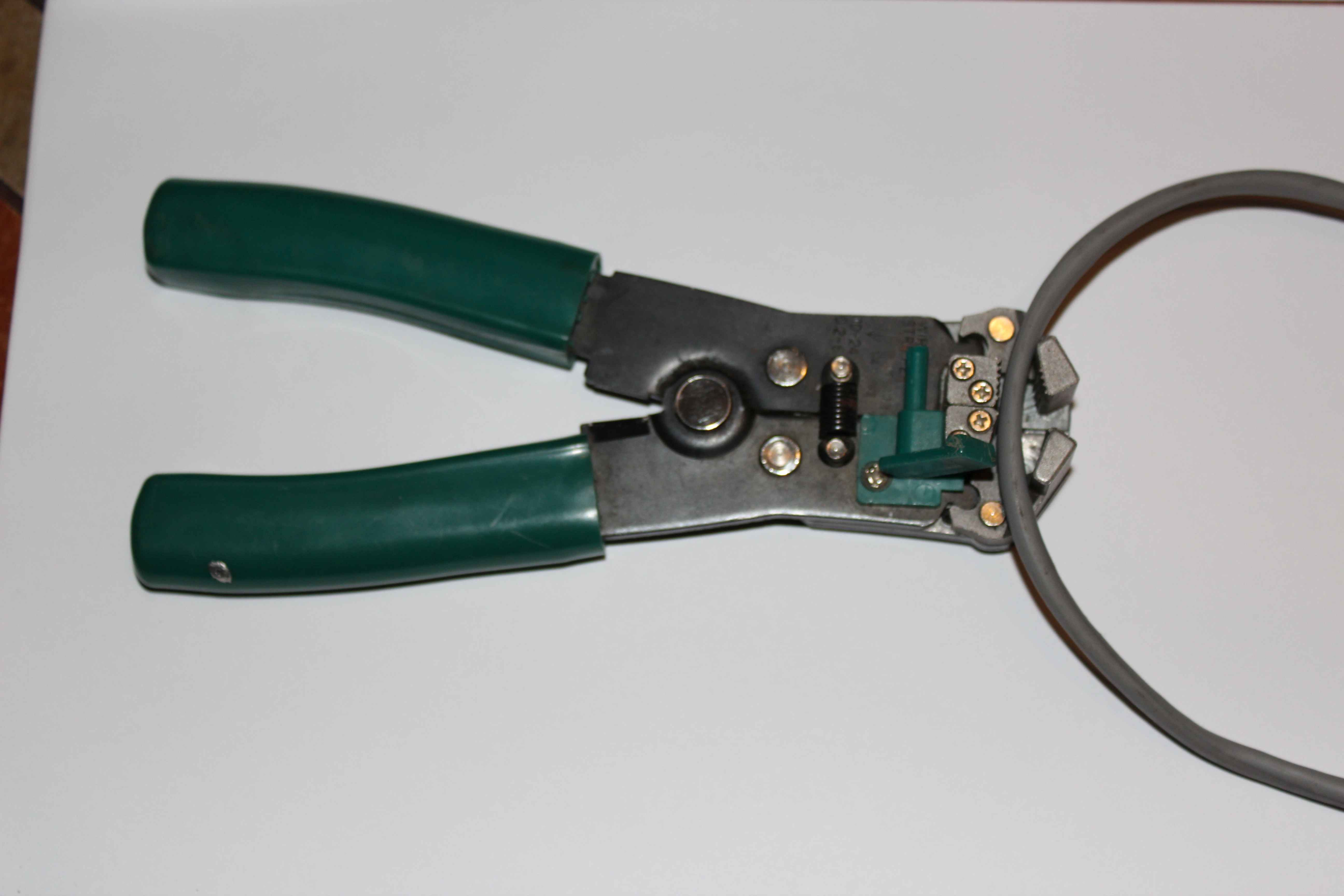
This will allow big time savings and the installation of several controllers and will significantly reduce the installation time.
Such a tool is much more accurate for removing external insulation and not destroying internal one. In addition, the cable length is adjustable.
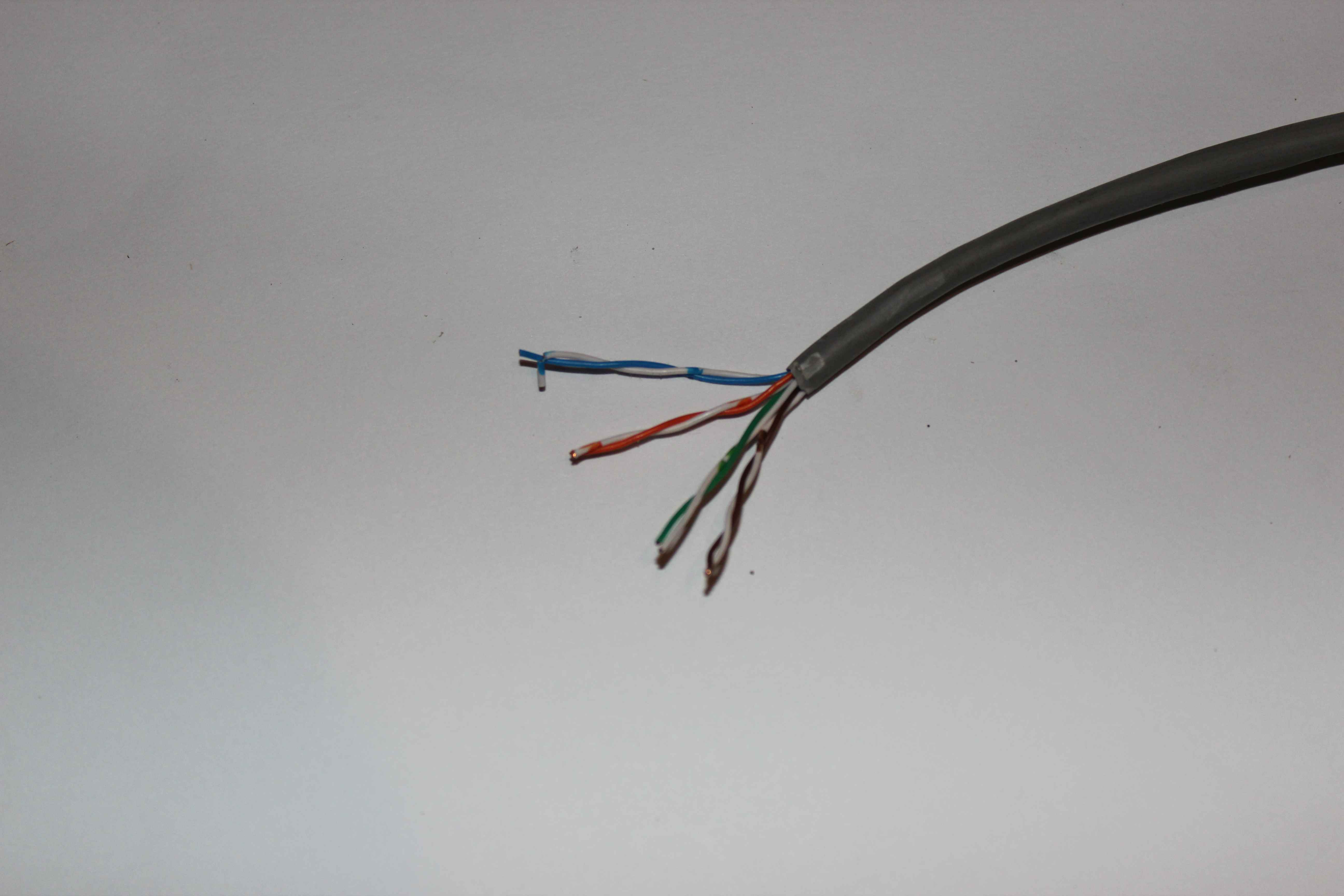
Communication and controller’s power supply uses UTP-8 cable (a standard twisted pair for computer networks LAN) or or AWT-6 flat cable.
As mentioned earlier, we are using only 4 wires, the other can be used as a spare or duplicate wires for the power supply.
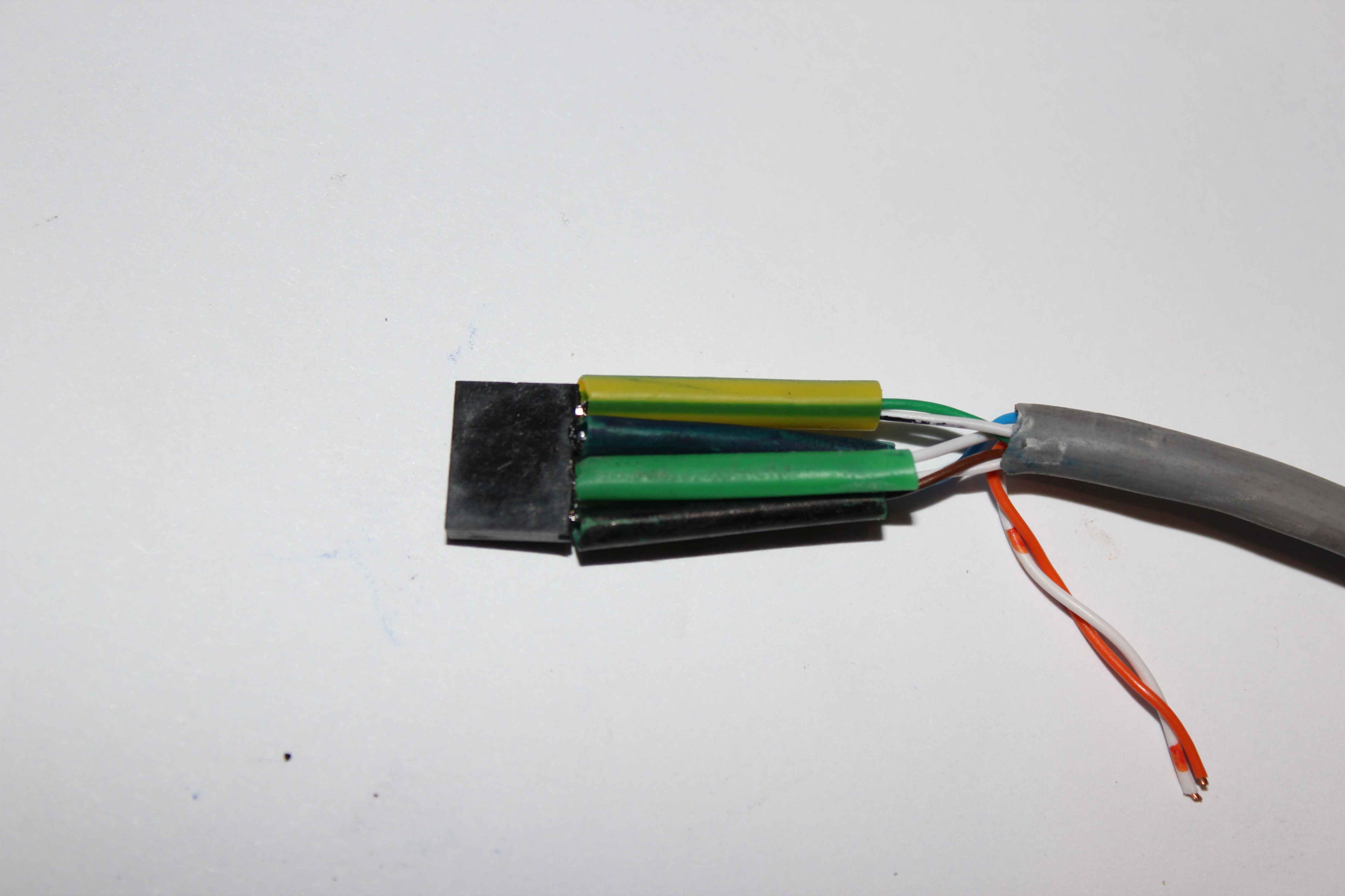
We are using the following color standard when connected to the controller
- 1 . GND , Ground , 0V ( UTP cable – 8 color brown and white – brown)
- 2 . CAN + – line databus non inverting ( white – blue)
- 3 . CAN – – Line databus inverting ( blue)
- 4 . + VCC (+9 . . + 25V ) – POSITIVE voltage power supply controller (green and white – green)
When you change the standard on its own you should ensure that the lines of the differential CAN+, CAN- were on the same pair of twisted wires, to minimize interference , which are much reduced in this way.
The CAN bus (Controller Area Network) is a serial cable so in theory should be leading from one controller to another.
Additionally it should ended with terminators (resistors 120ohm) at both data bus ends.
However, in the event of damage of the serial bus, is very troublesome to determine the point of failure and segments for the damaged node lose communication.
In the event of a short bus wires all devices stop working, and finding damage like looking for a needle in a haystack.
Therefore, we recommend the installation in a star architecture on each floor of the building, bring each wire to one place, and install only one terminator in the middle.
It greatly simplifies the installation service in the event of damage of the bus cables. In such a system , we can repair the faulty segment.
Star installation type requires extensive tests before plastering the walls, because for larger object you could have communication problems.
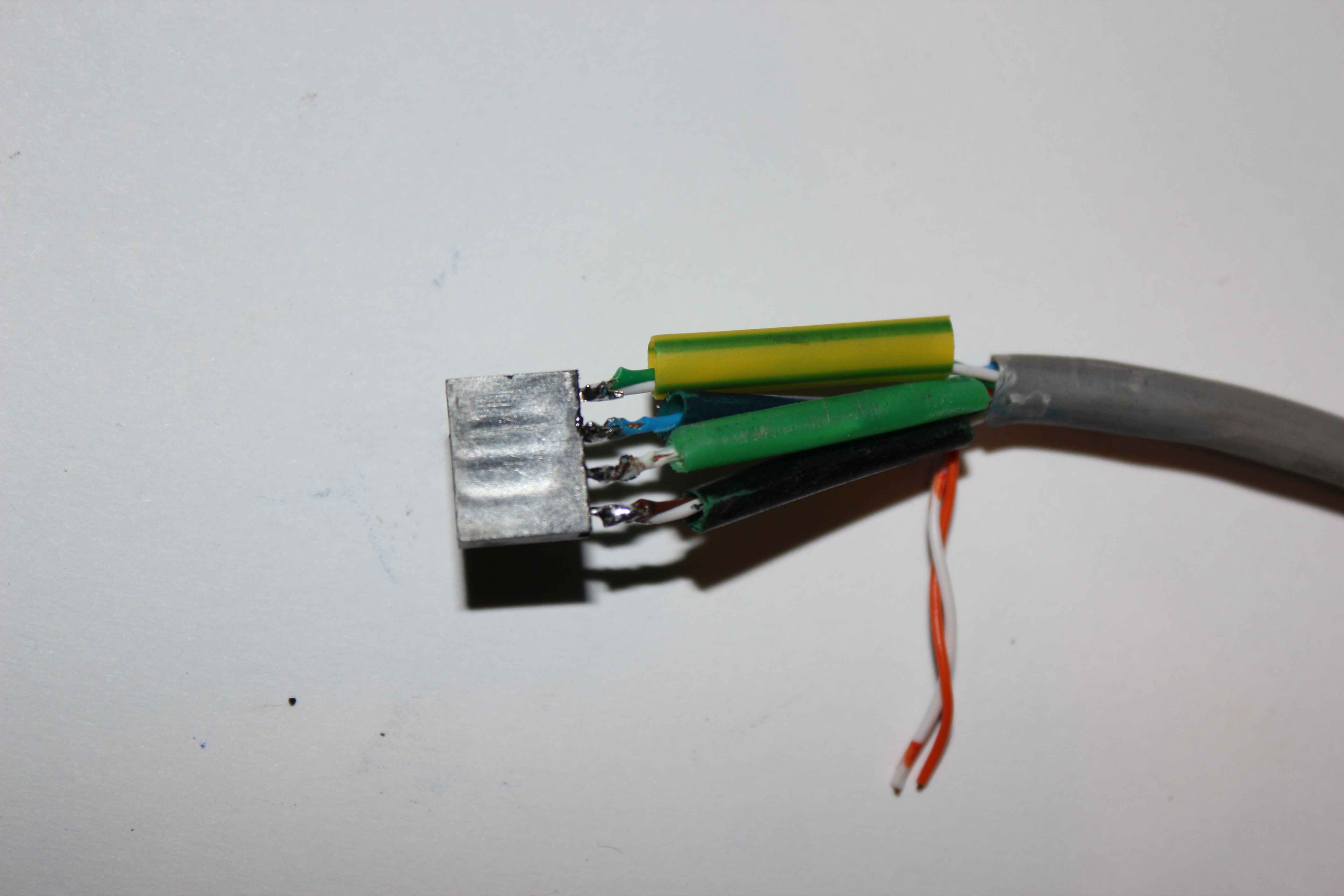
To connect the bus you can use any connector 4 pin female with a pitch of 2.54mm.
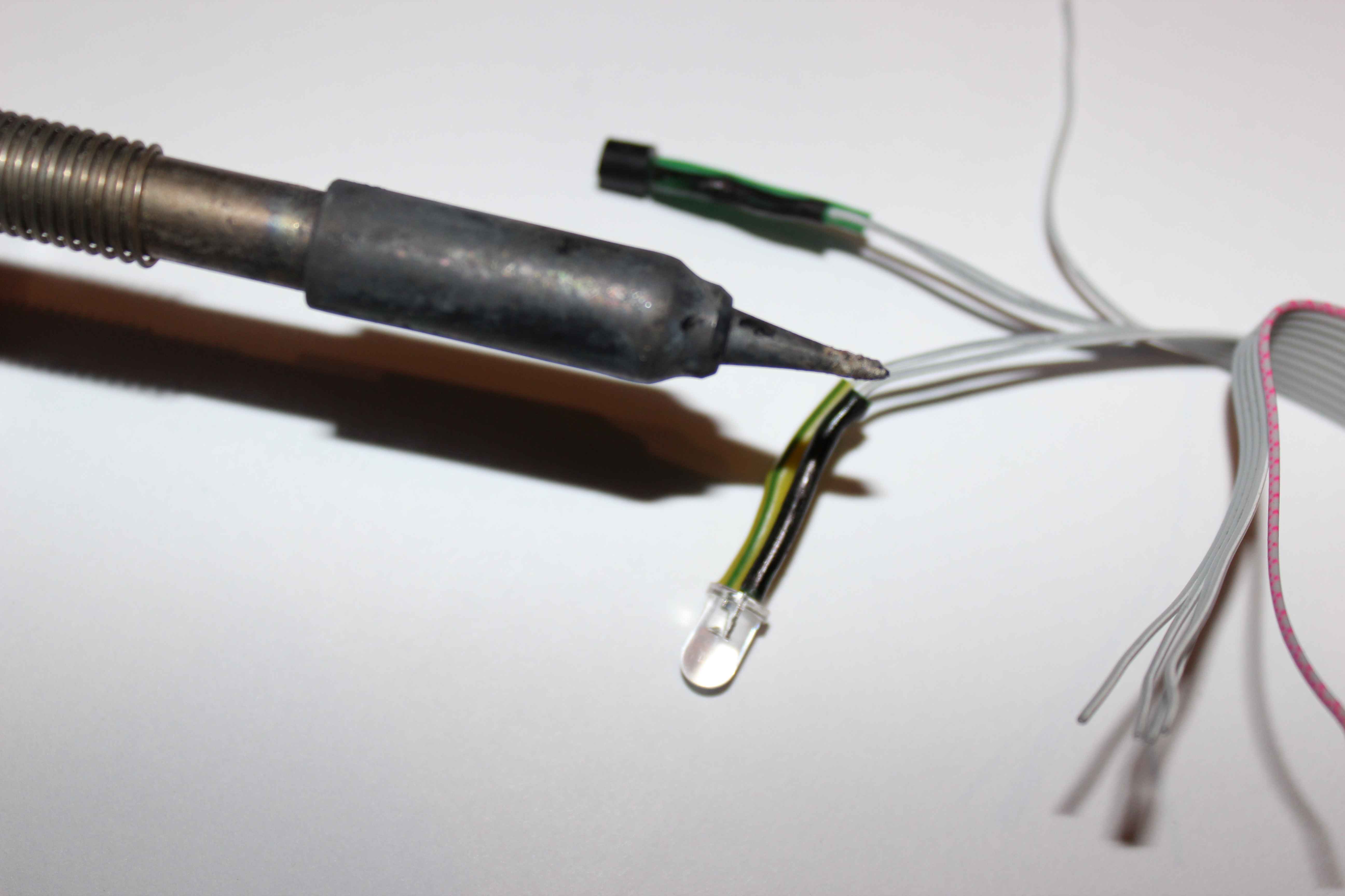
In our case we used a solder connection which, despite prolongation of installation time, certainly increase the life and performance bus.
In the case of soldered joints need to use heat shrink insulation to protect against accidental short circuits.
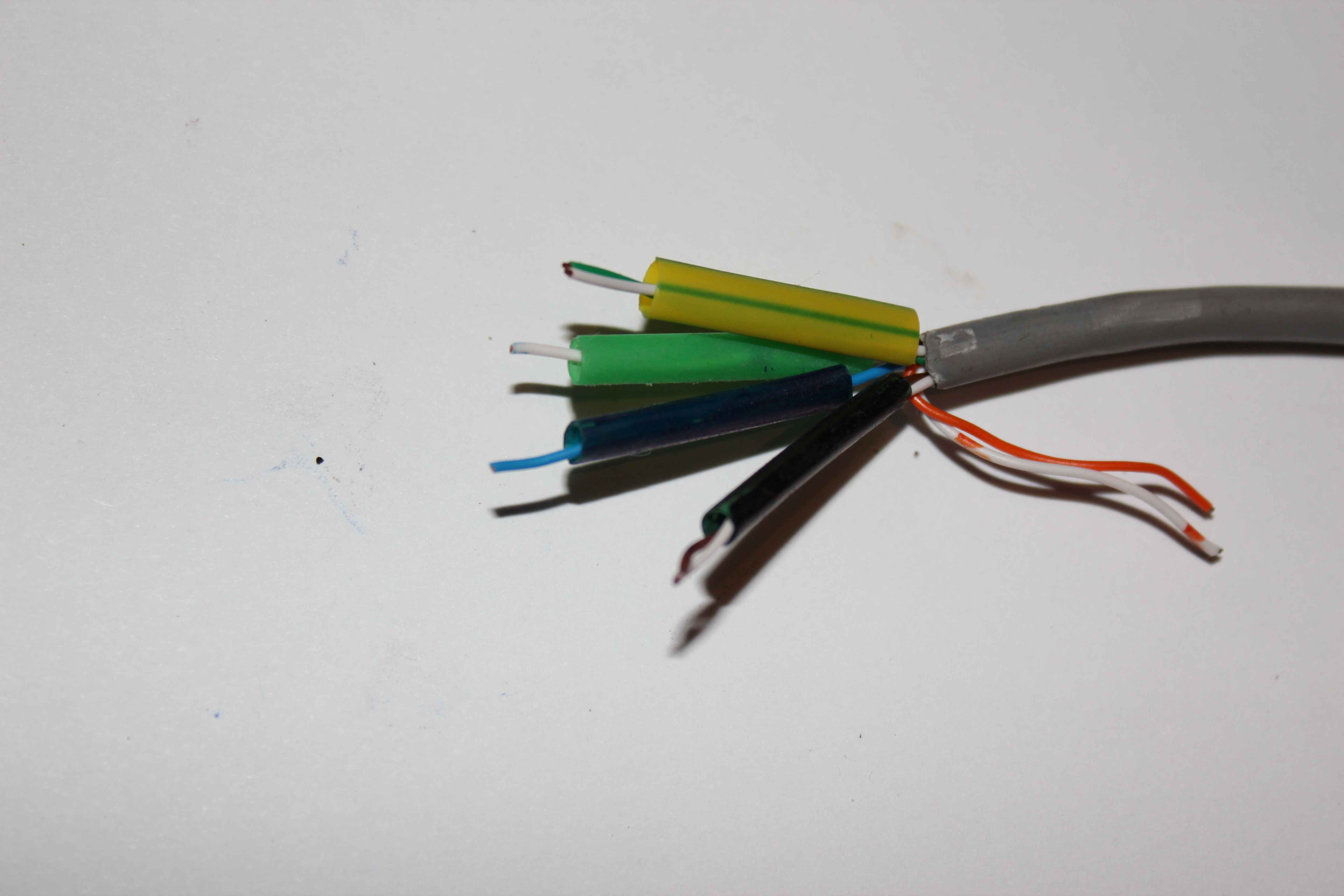
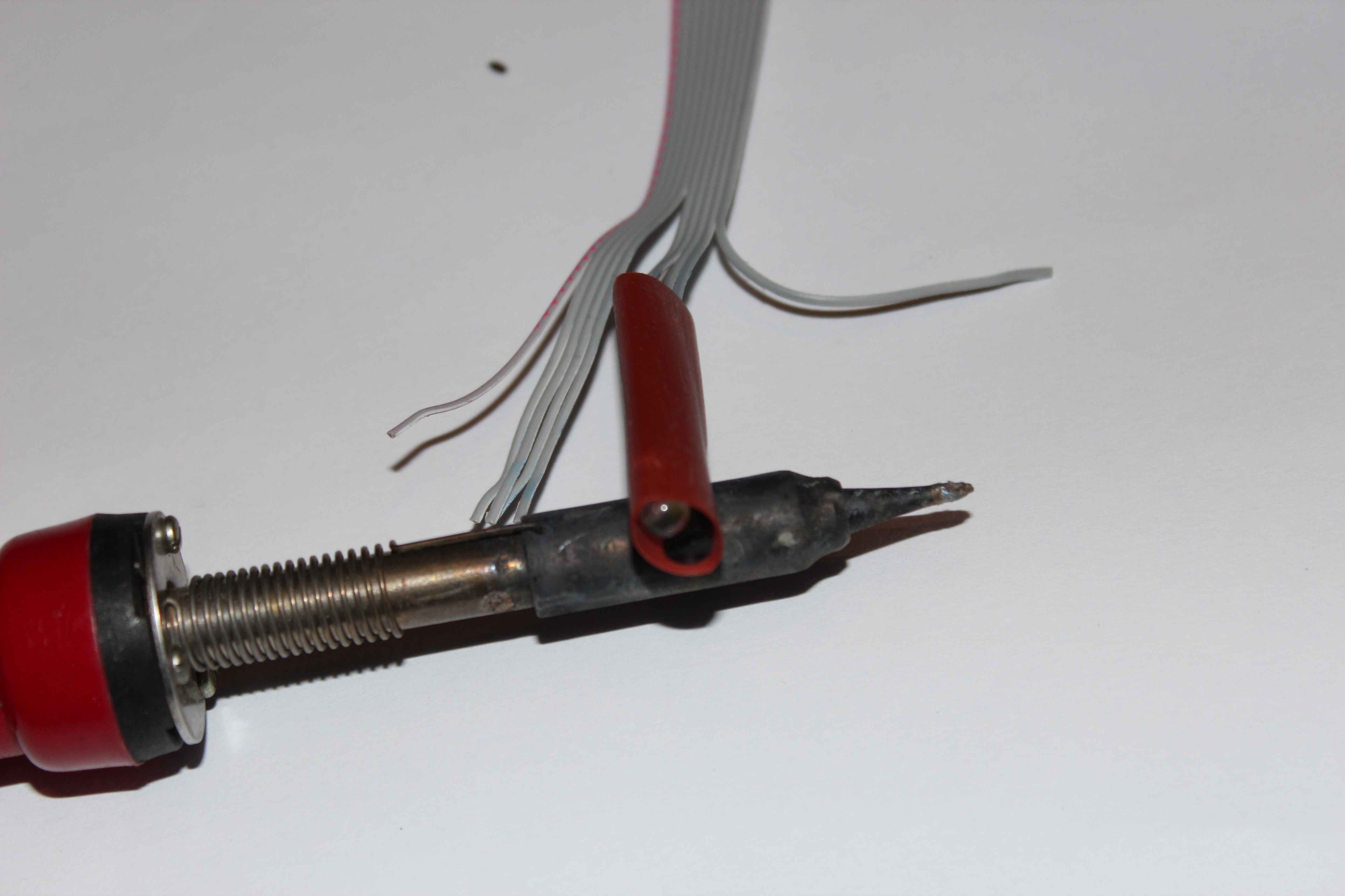
After soldering , carefully stretch shrink to isolated wires and a soldering iron to heat them to have shrunk.
T-shirts are best used in a variety of colors, making it much easier to work.
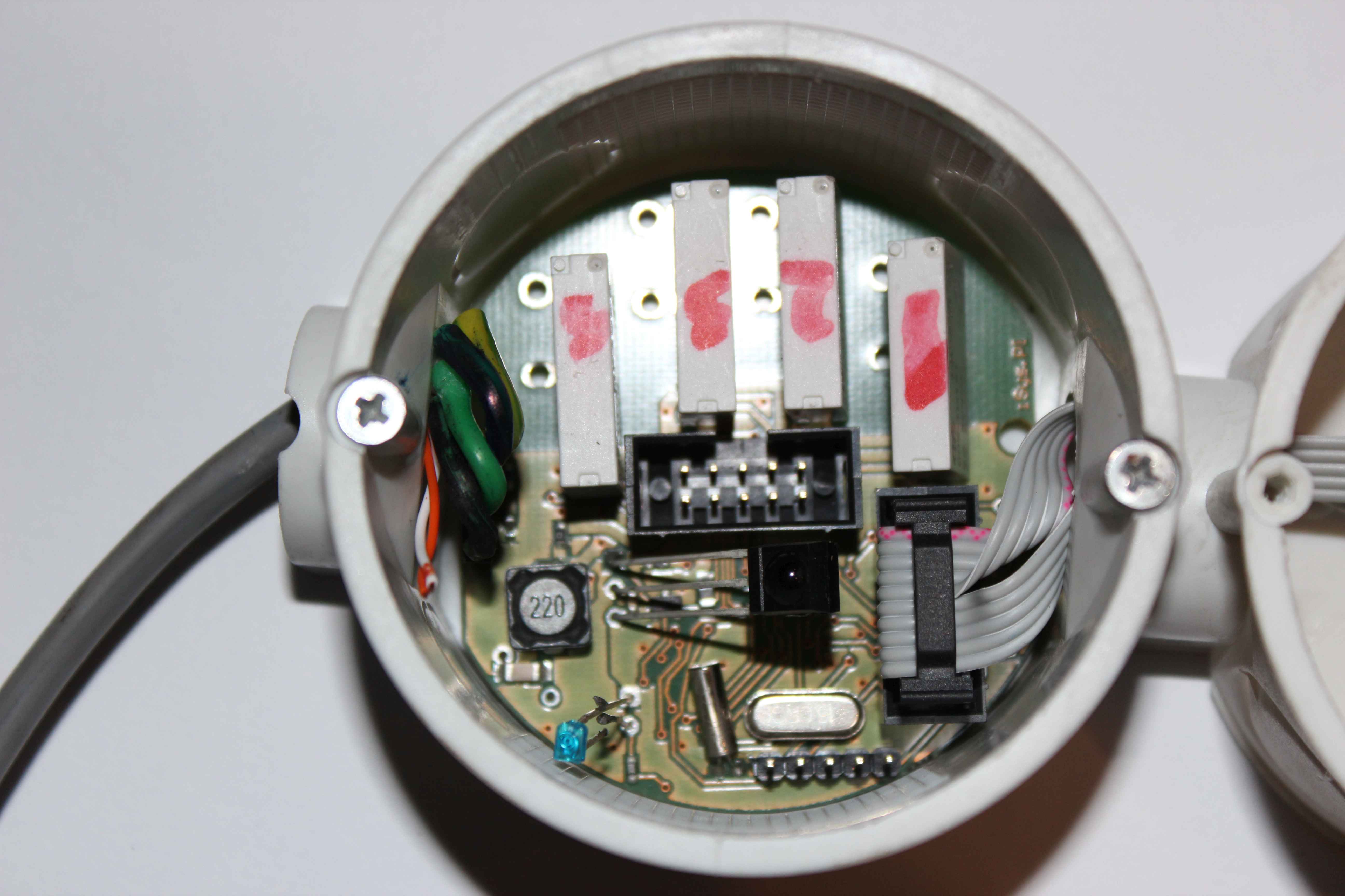
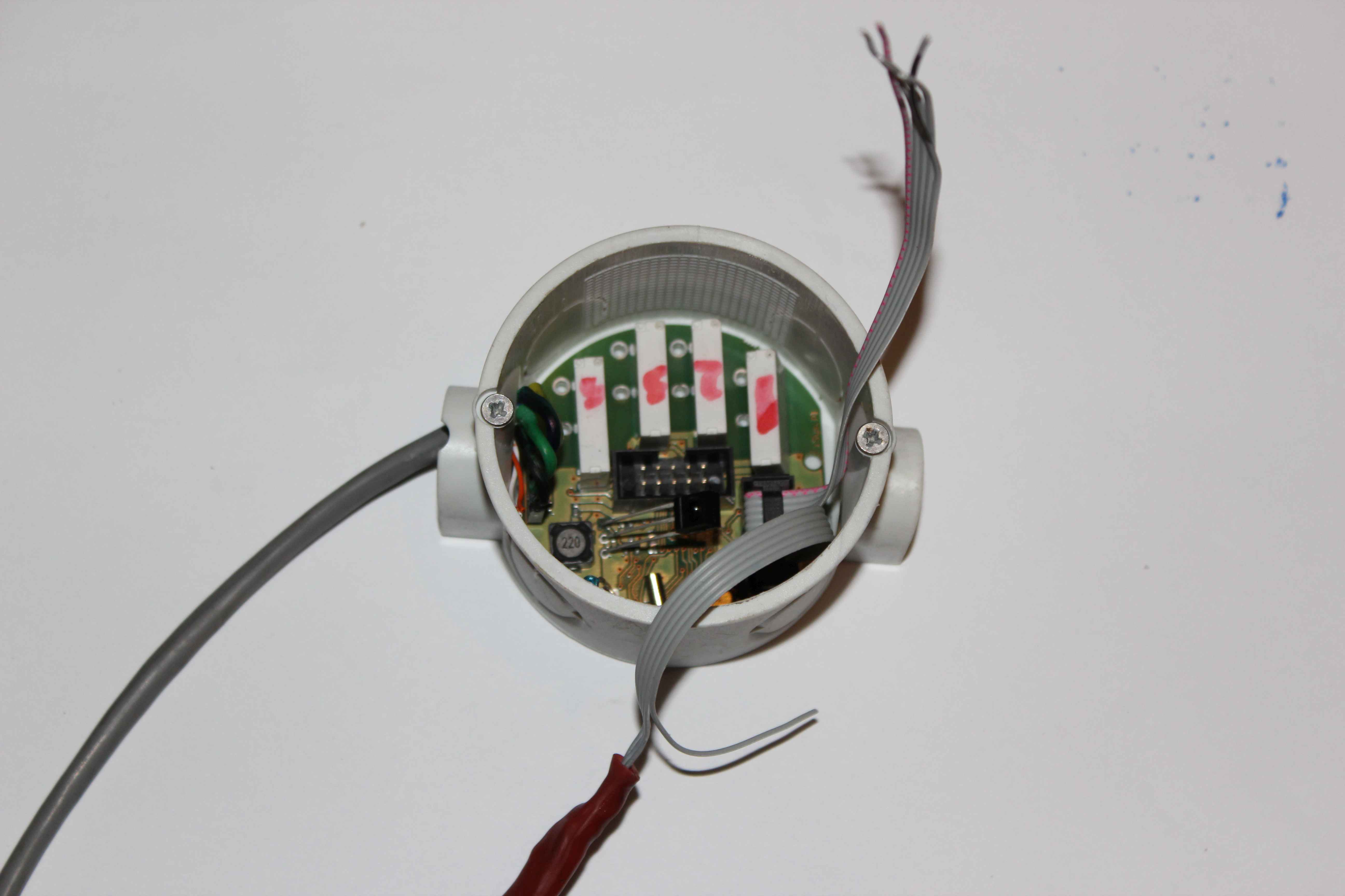
Bus connection and power supply to the controller (voltage).
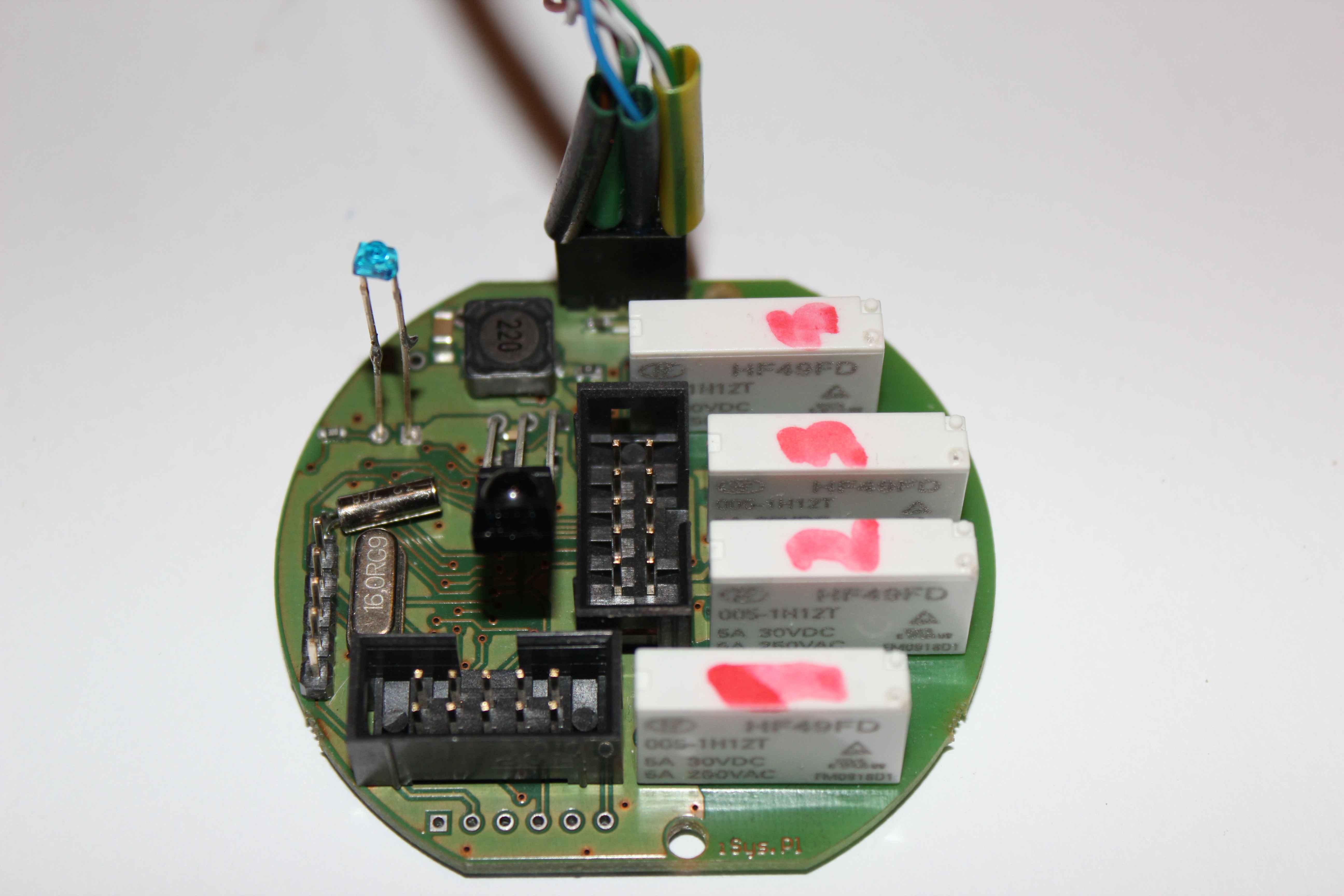
The next step is to create a connections to the switches and sensors.
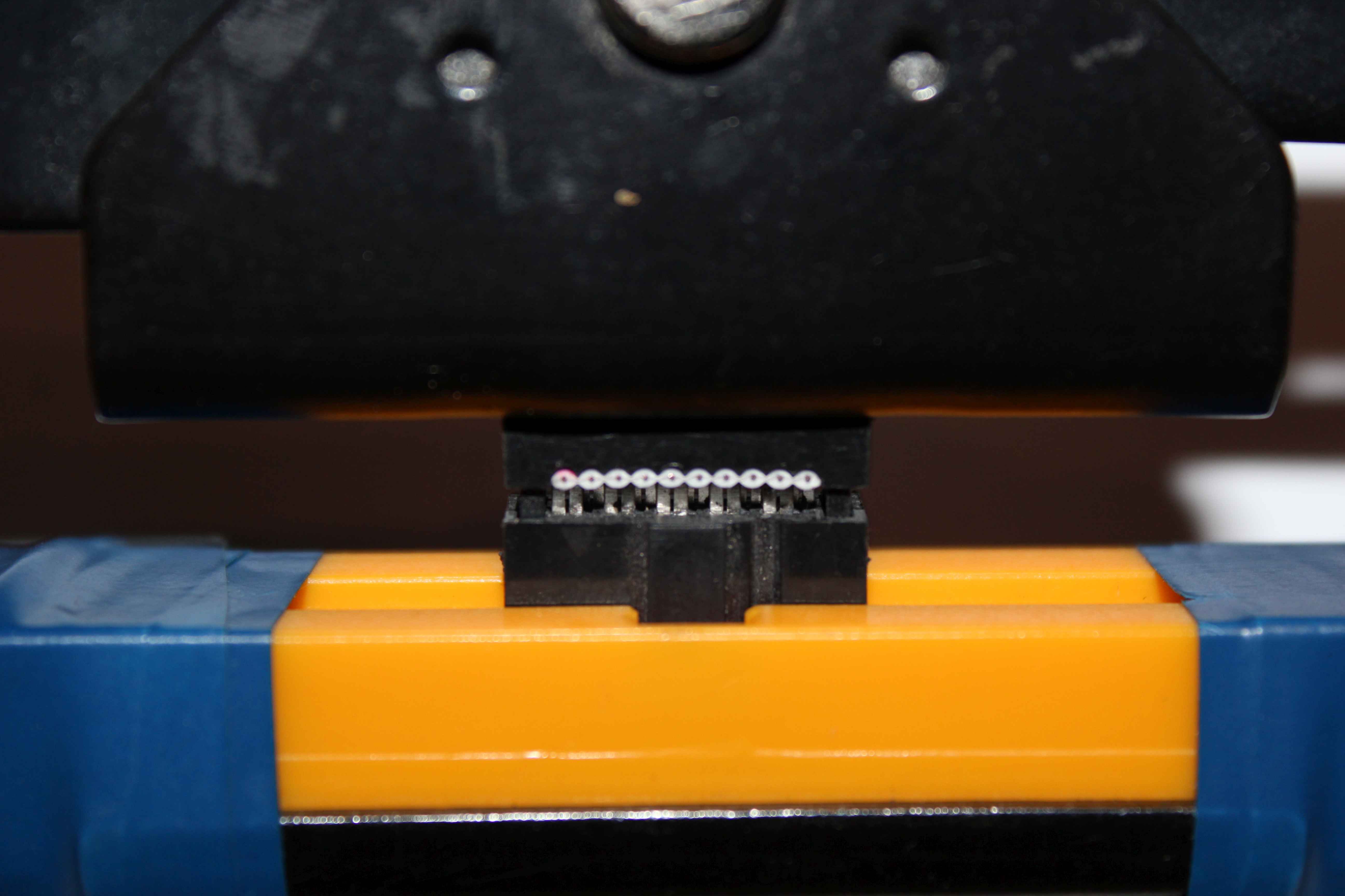
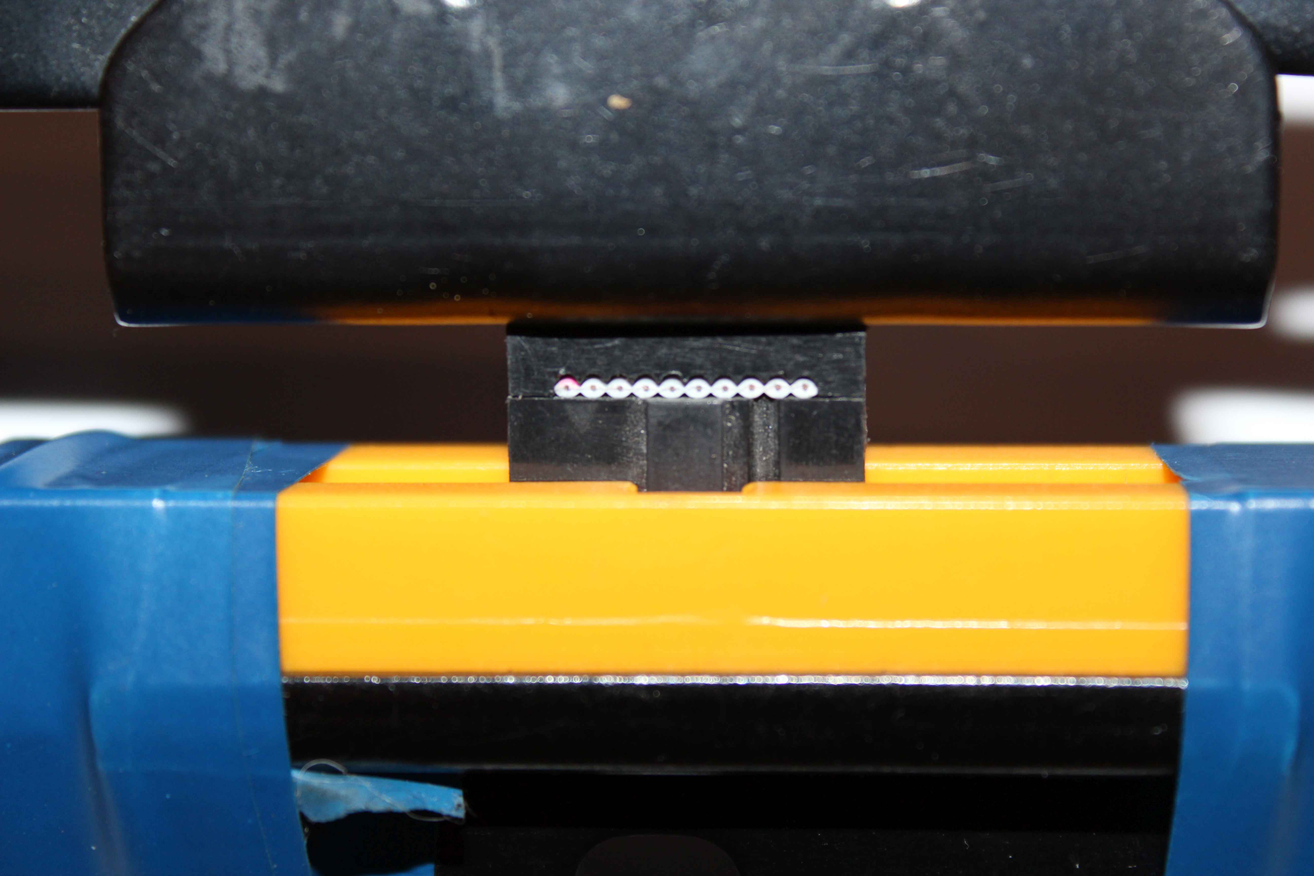
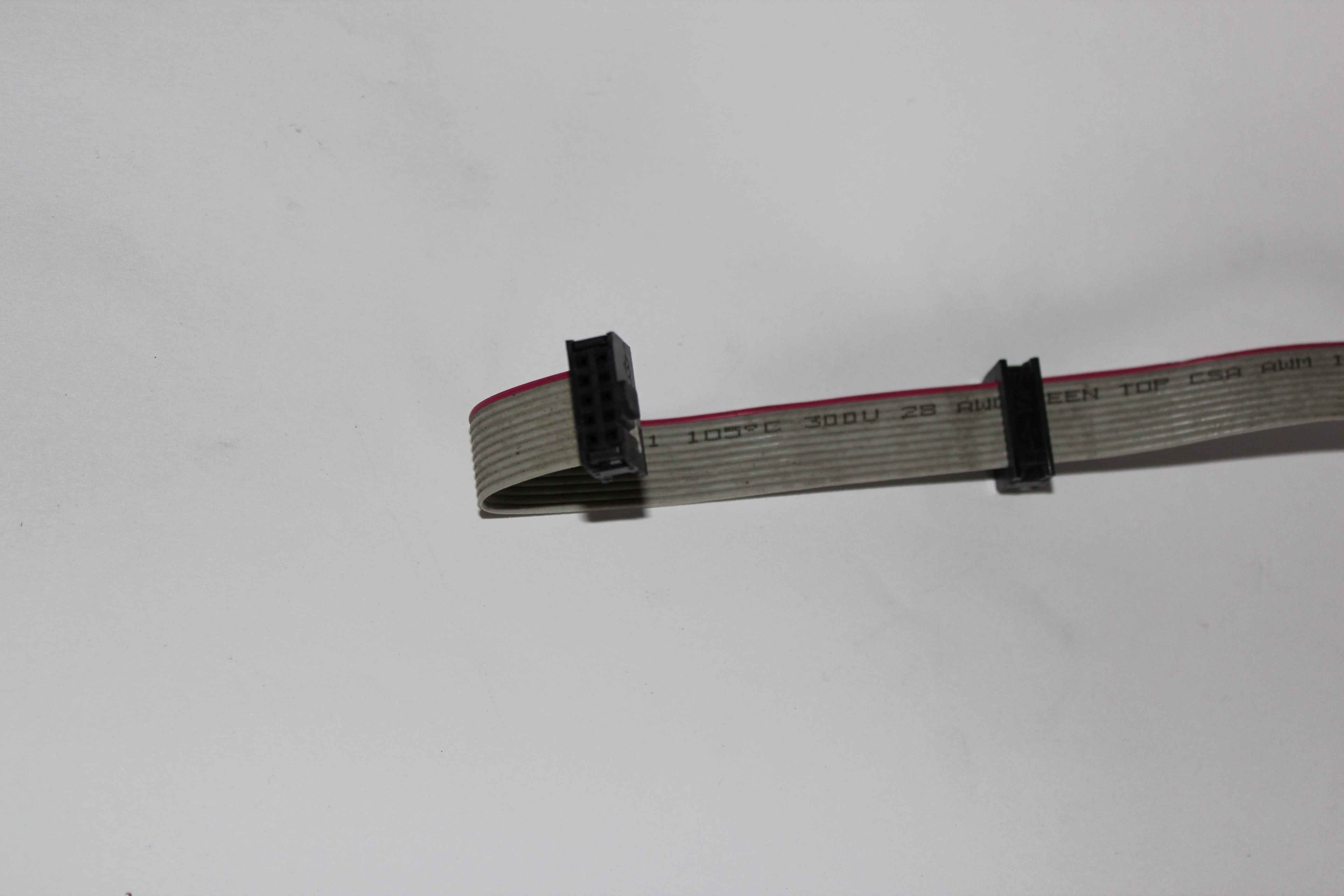
This is done using 10 pin flat cable and IDC connectors.
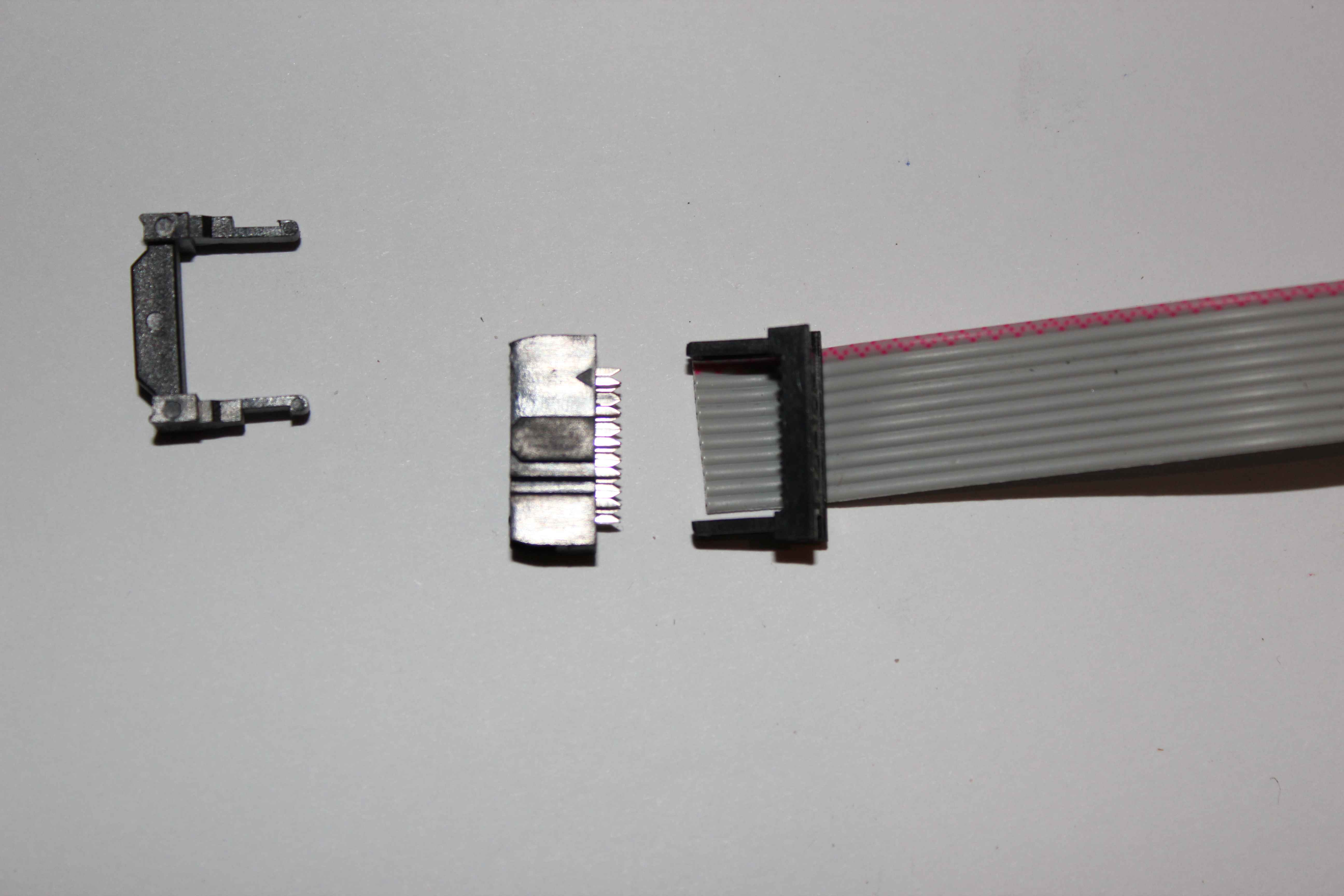
clinching performed crimper IDC.
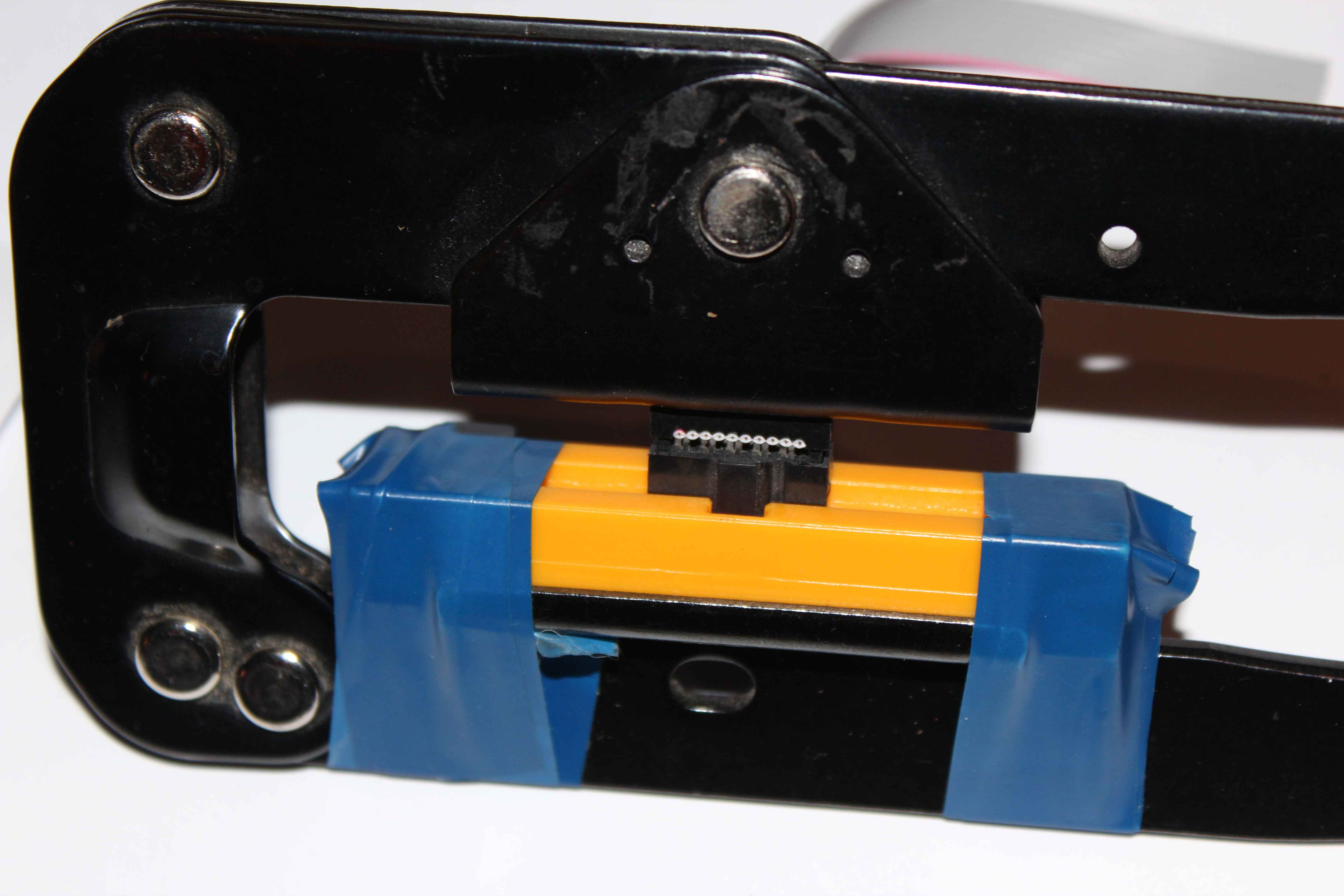
For convenience, the red wire is pin number 1 . On the socket pin 1 as indicated by the arrow.
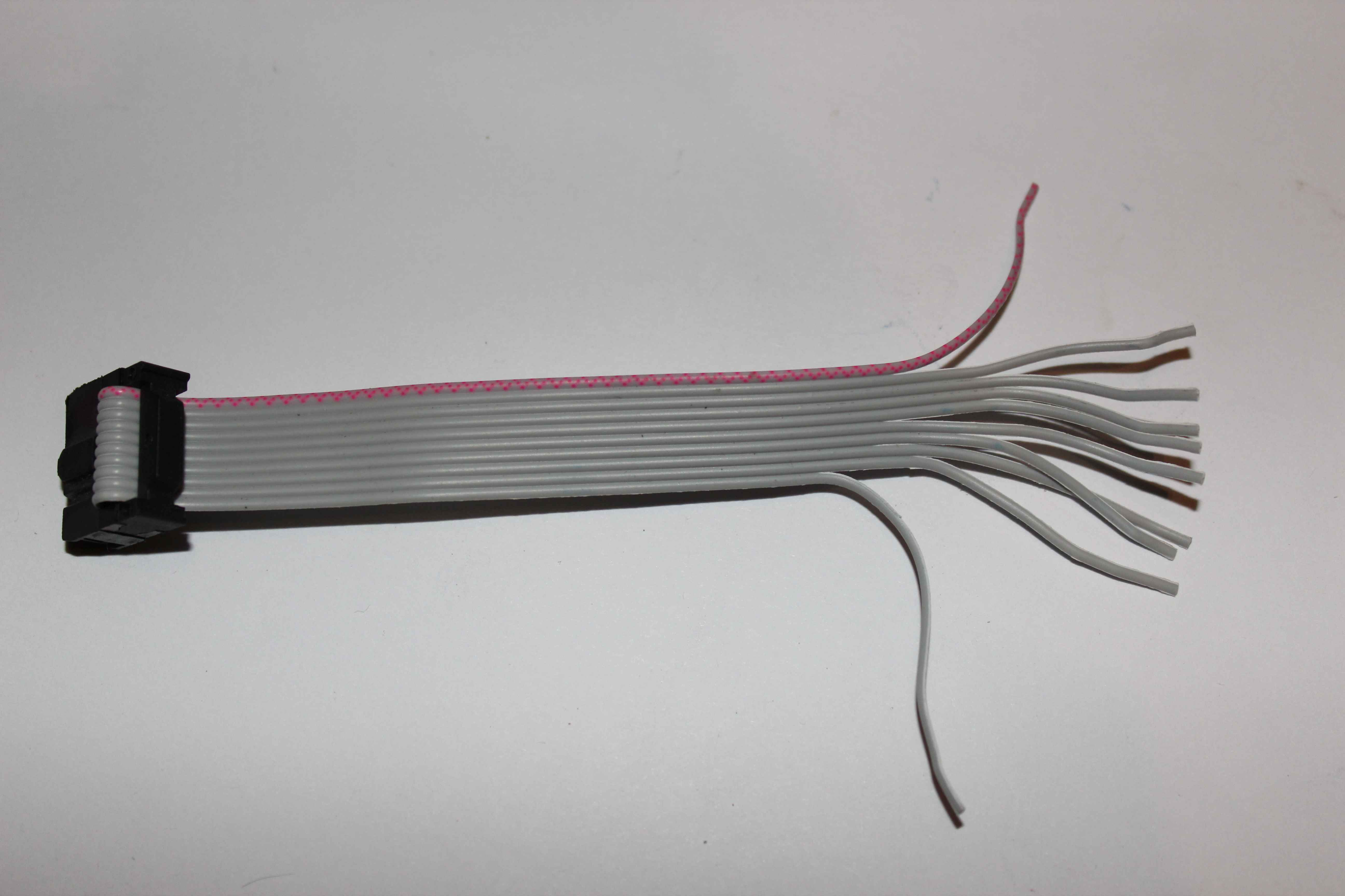
The length of the cable used depends on the number of cans , in which we intend to mount switches.
The safest way to do with a supply cord and canned just cut to the required length.
Cable should be distributed over a distance of a few centimeters and uninsulate only at the ends that are going to connect.
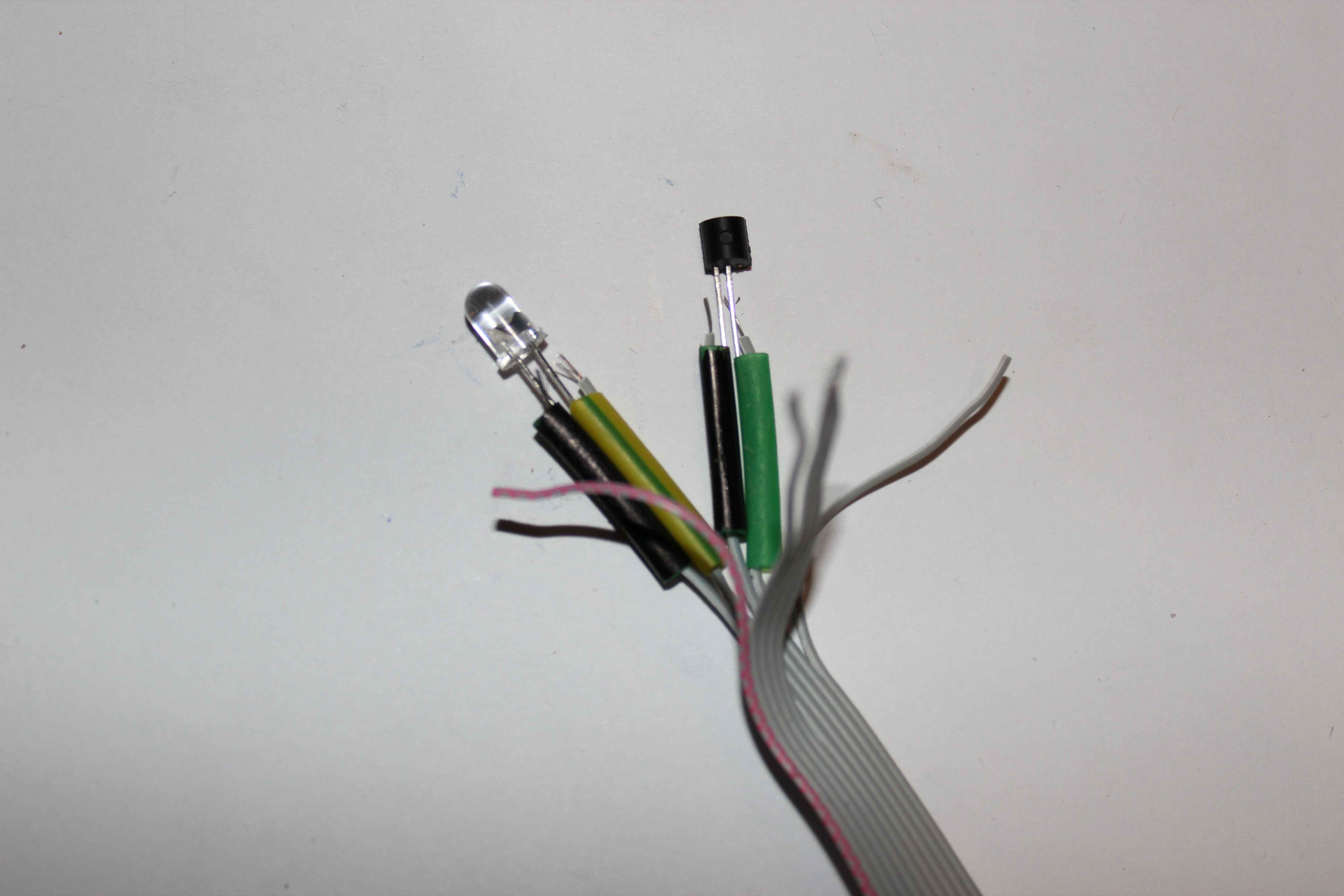
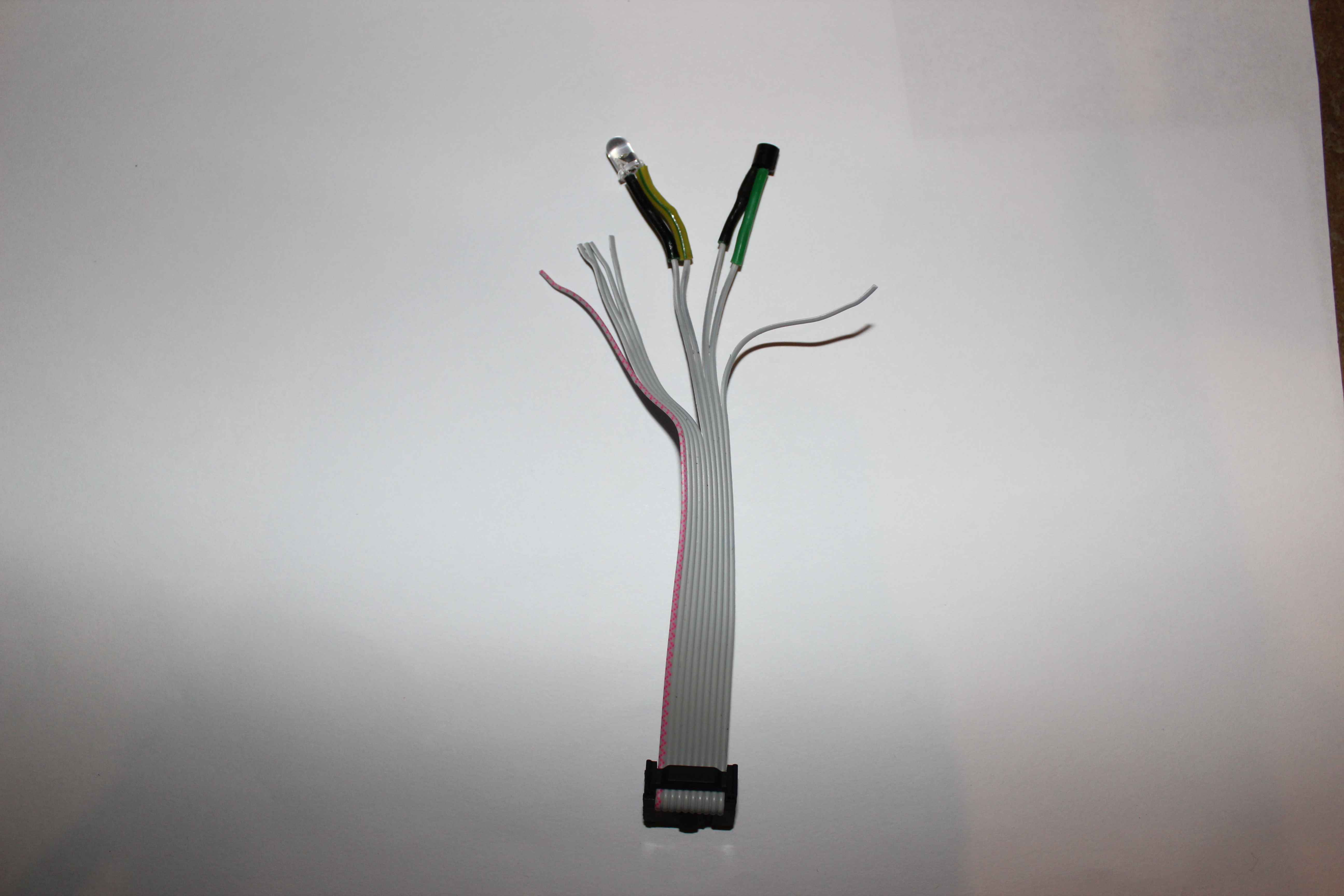
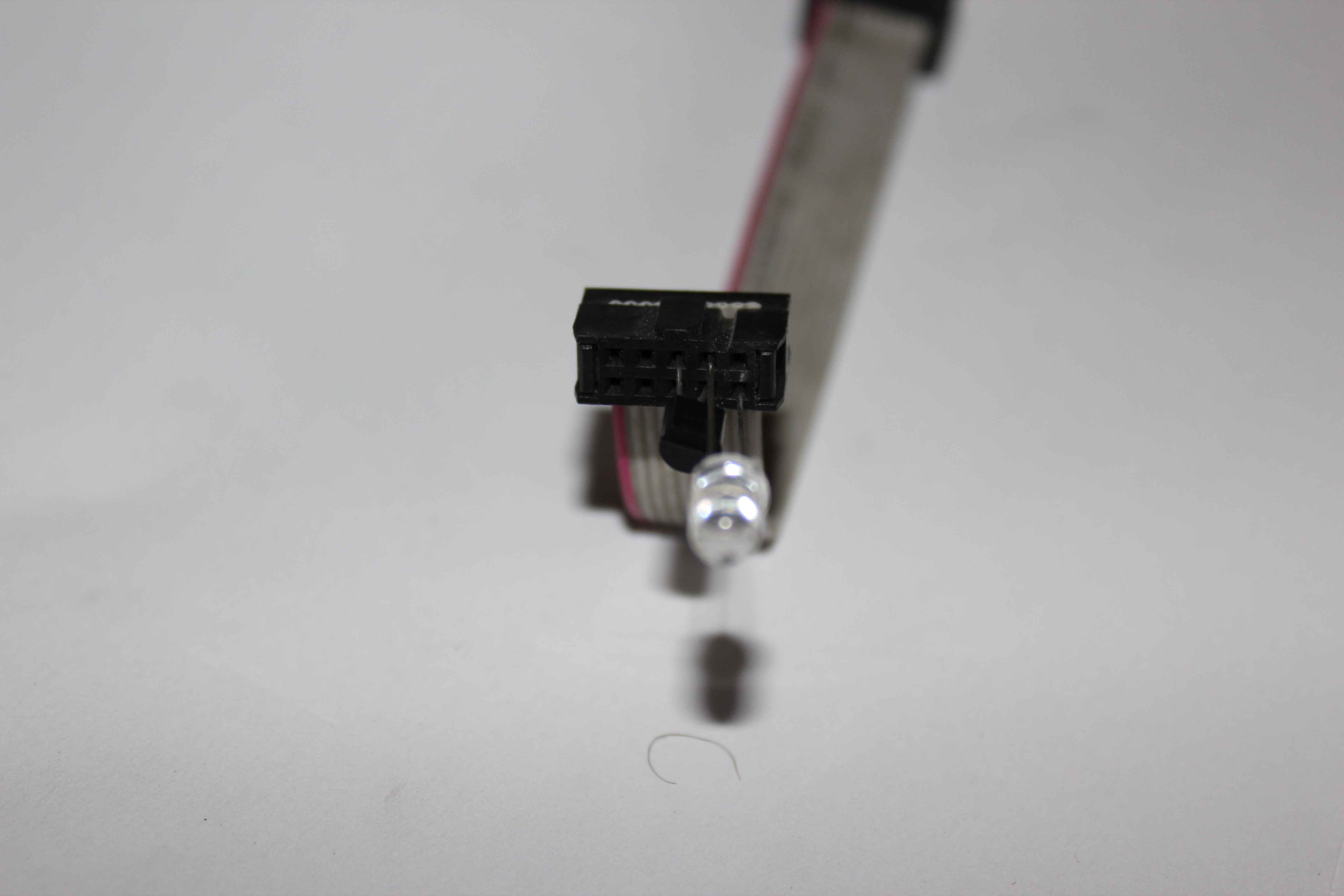
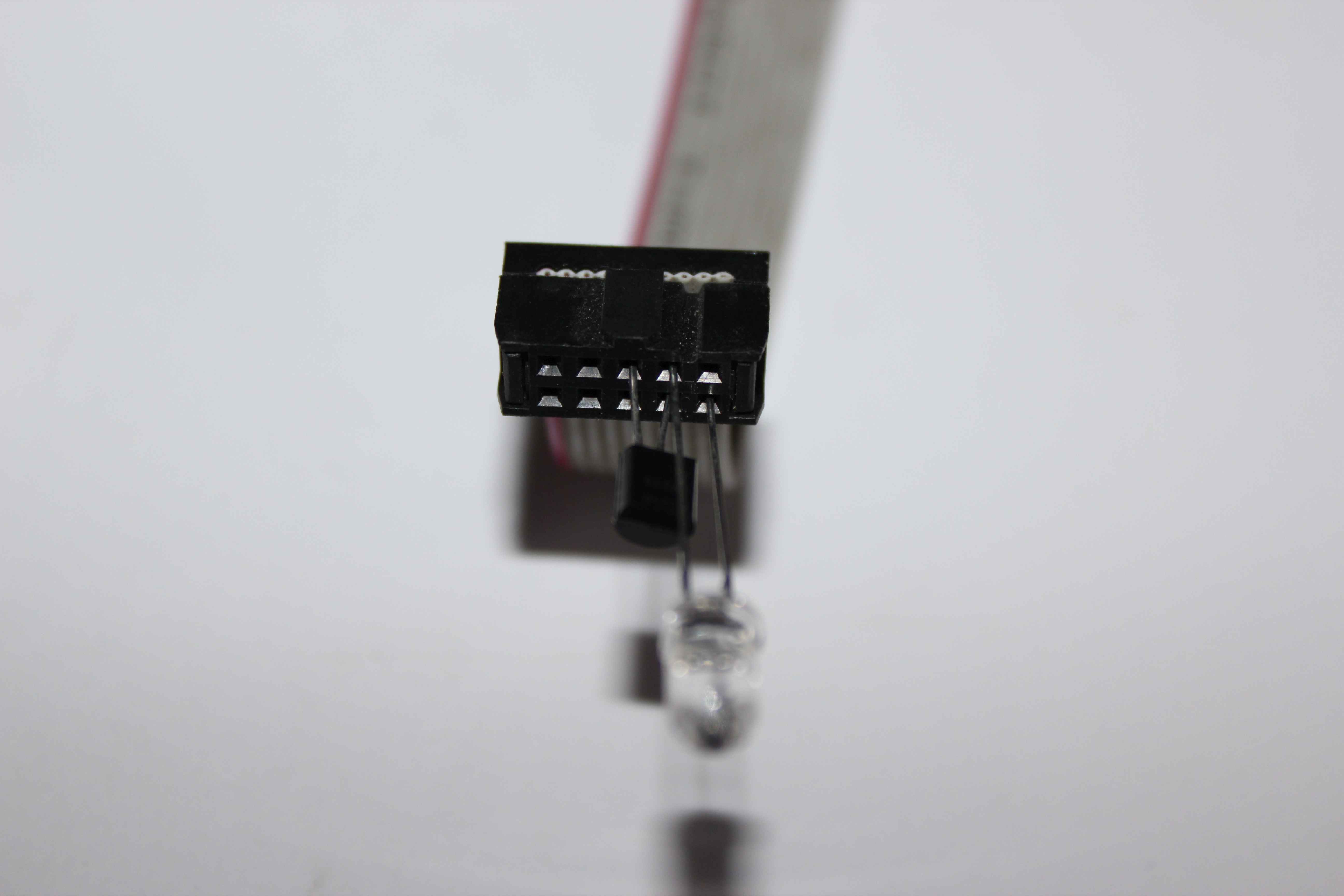
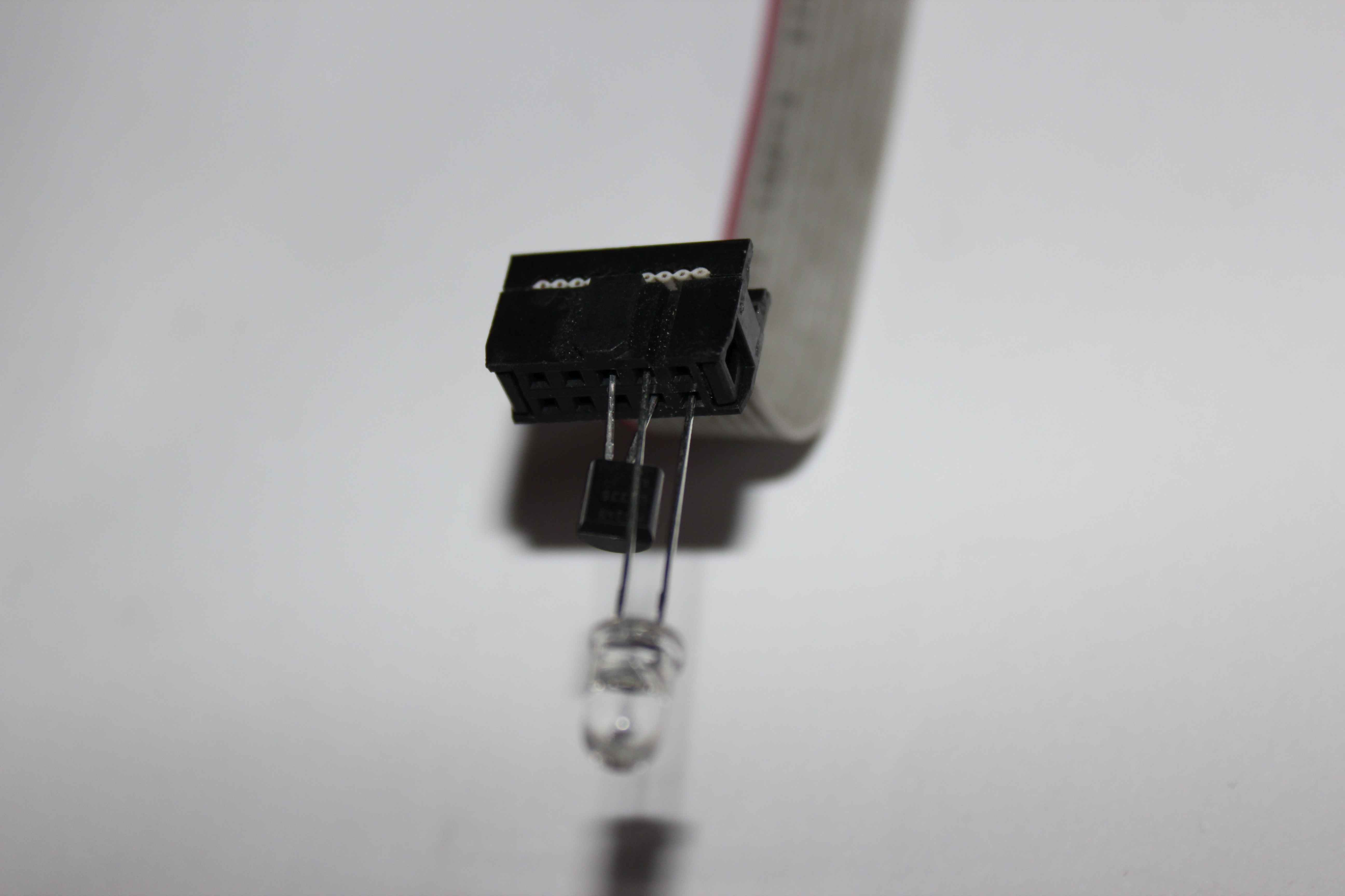
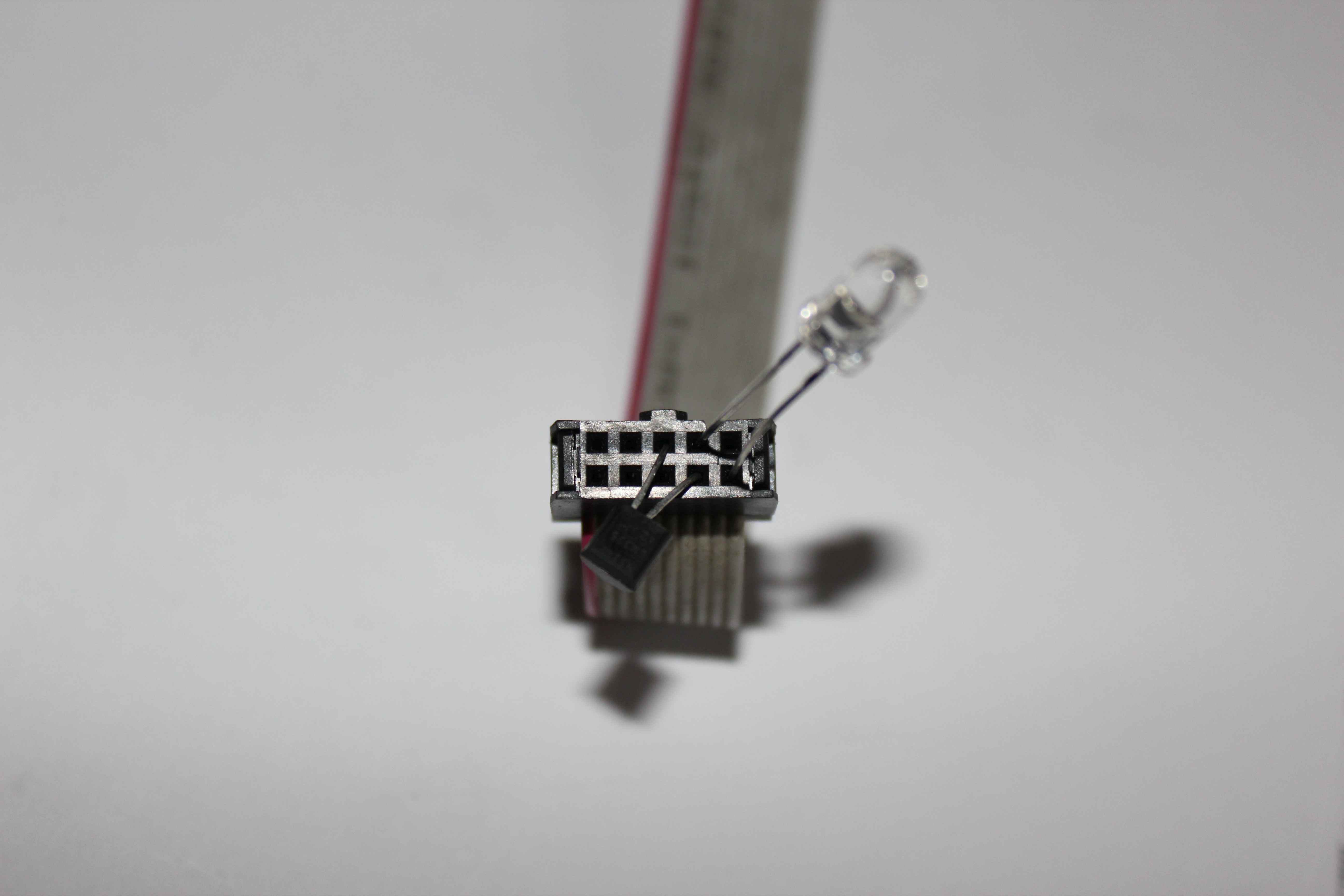
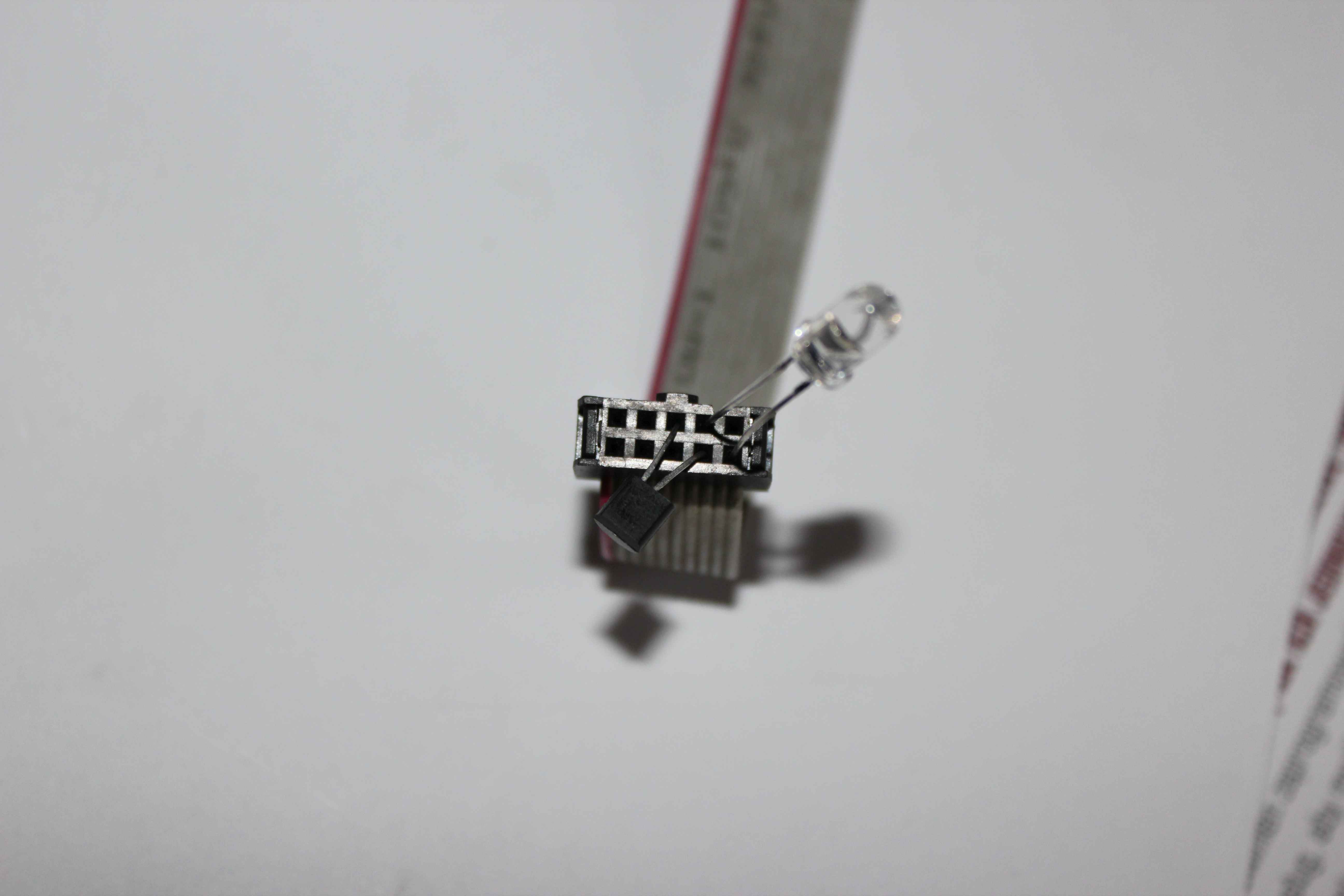
Examples of self- performance sensors Lighting and temperature.
As the temperature sensors we recommend using LM335.
Both measurement inputs are designed, that the power input takes place in a secure way. Short-circuit inputs to the internal ground, the internal power supply (+ 5V) or reverse sensor does not damage the controller nor the sensor.
The erroneous sensor is connected just get meaningless measurements from outside the boundaries of normal temperature.
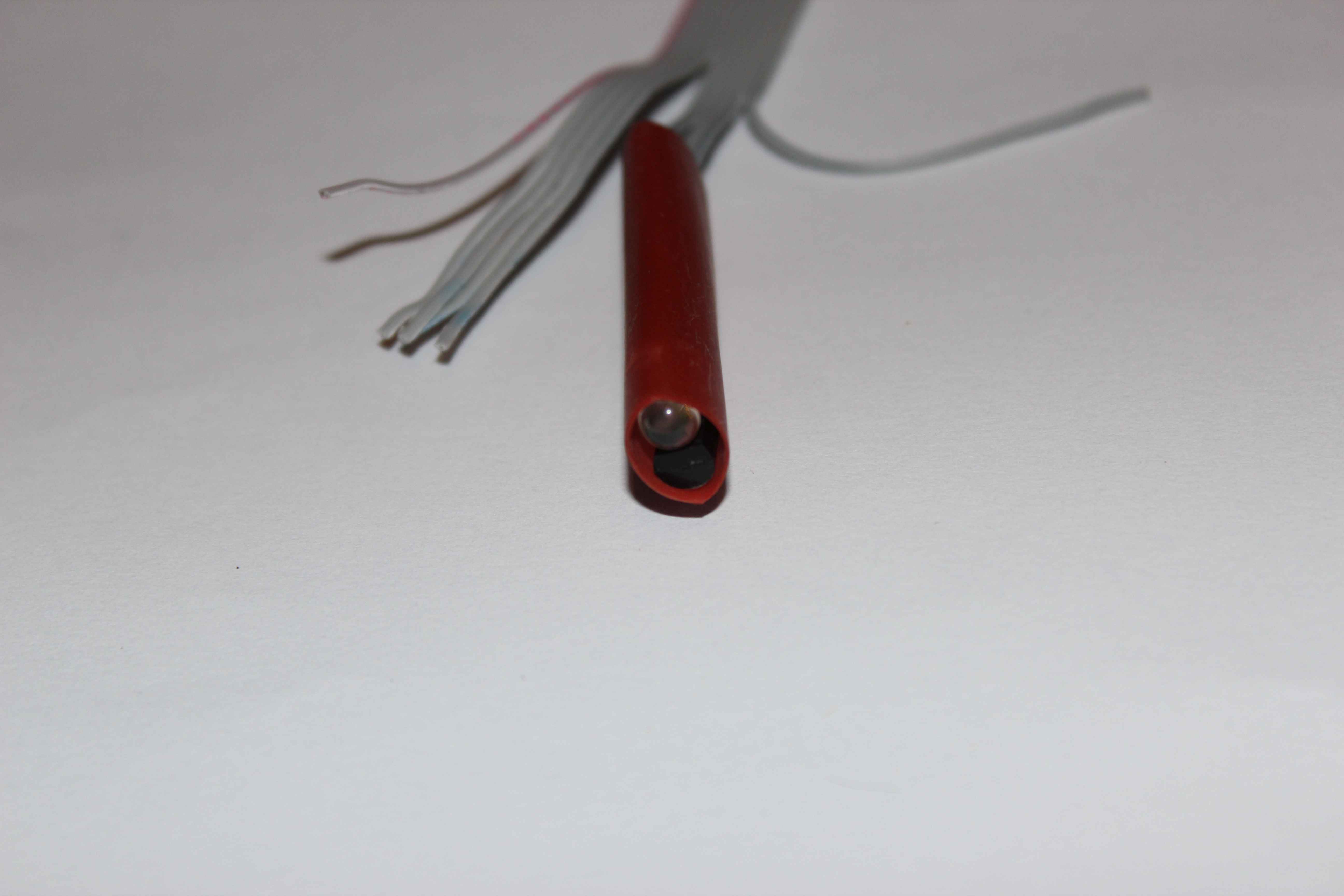
LM335 sensor has 3 pins of which one breaks off the same housing , repeatedly moving wire.
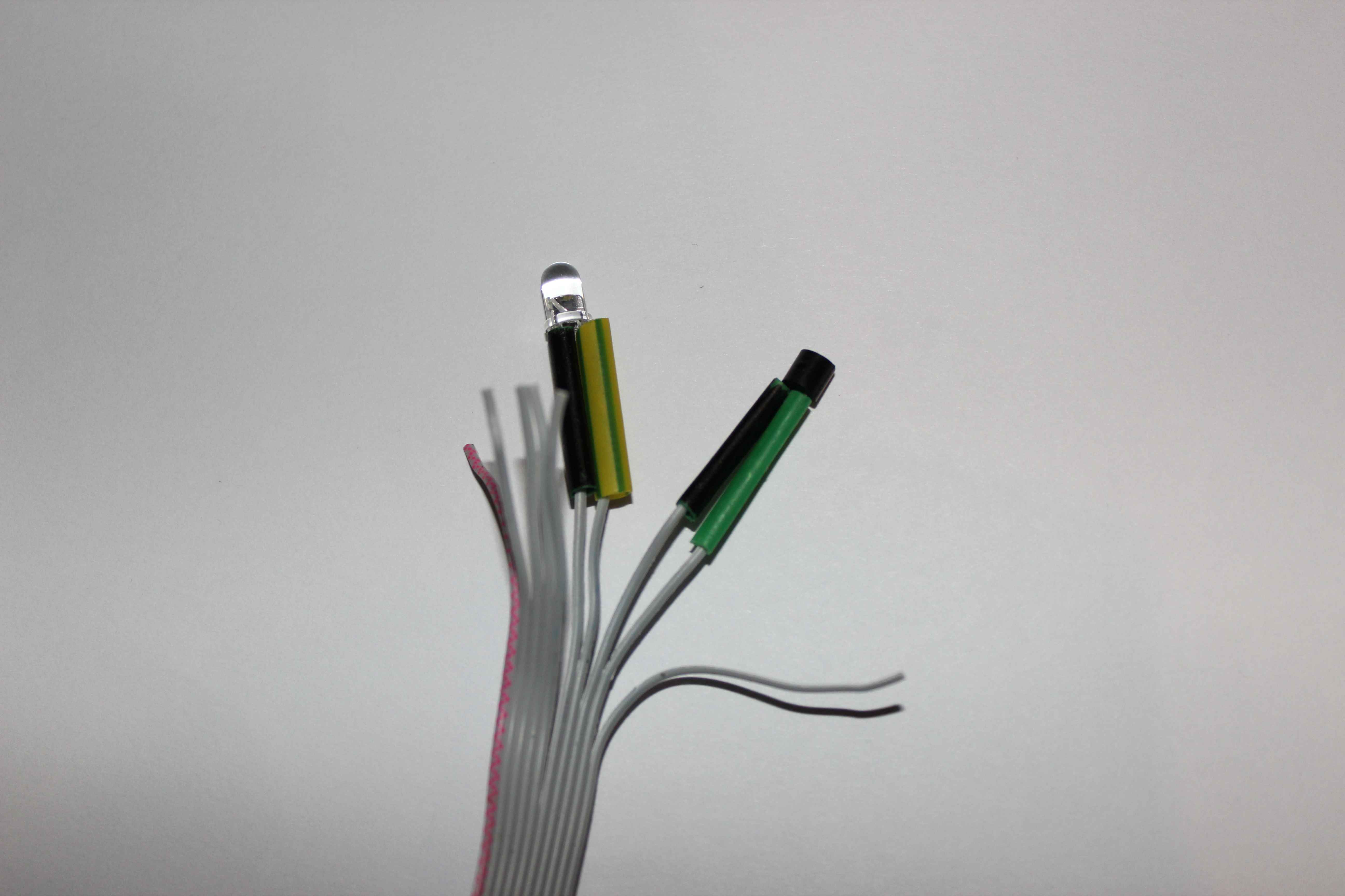
We put shrinkable insulation to bare wires before soldering.
As the colors we used standard:
- Black : 0V , ground , GND – common wire (-)
- yellow – green : light sensor photo – a transistor or a photodiode (+)
- green sensor (+)
As a light sensor , a conventional phototransistor or photodiode should be used.
The phototransistor can be installed internally in room or outside for measuring light level. If phototransistor is connected the opposite way (+) and ( – ) it gives flatter characteristics.
Photodiode installation: cathode to (+), The anode (-).
When photoresistors is used you should select the appropriate value of resistance about several kilo ohms.
After verifying the correct operation of the sensor measurements, we can ensure insulation by heating heat-shrinkable insulation tube.

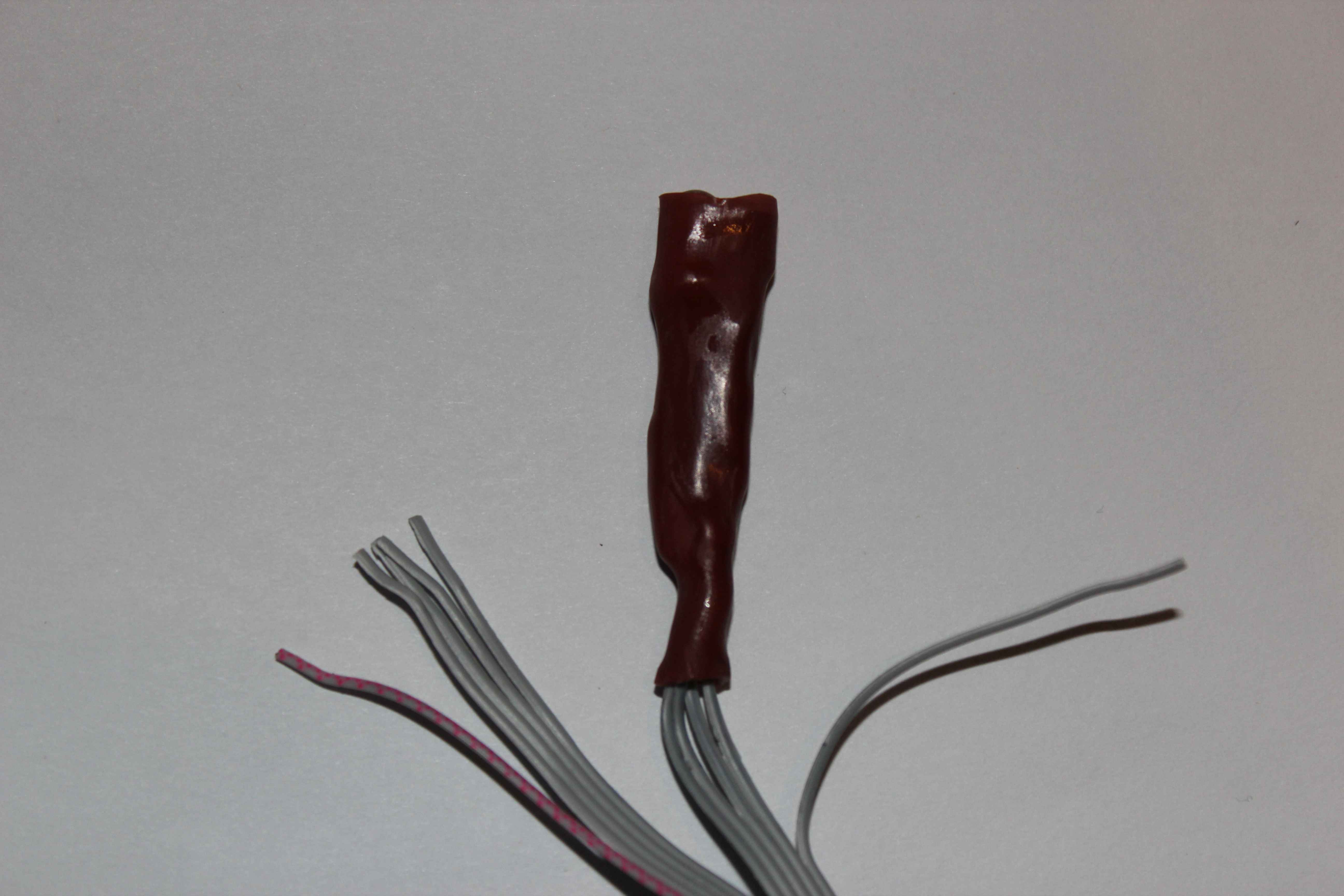
If you wish to install sensors in locations exposed to high humidity, sensors must be absolutely insulated electrically, “against water”, hermetically sensor and cable . Failure to meet these requirements is like “sapper mistake” and will cause incorrect operation , resets , hangs the controllers or damage.
It can also affect other controllers in the network .
Please keep in mind the following rules:
- Cable must be leaded without connecting, sharing, division from the sensor to the wiring box
- with lengths greater than 1 meter shielded cable should be used ( shield on ground , 0V)
- repeatedly dipped in epoxy resin in a period of time to allow drying
- put sensors “metal cap” and pour resin to seal it. In the case of the light sensor cap must allow light to pass to some extent
- sensors must be placed away from electrical appliances , outlets , etc.
- secure the cable and the sensor from damage and ensure full electrical isolation and against water in a moisture
- sensor mounted on top of the cap to the top of a wire frame in the shape of a siphon so that any moisture dripping on the bottom ” siphon ” and does not lead the cord on to the lowest point
Non measuring inputs can not be connected to external voltages which also occurs in the case of improper insulation of sensors and cables, in the case of transient, break, interference, surge.
In cases where there is no complete isolation , from surges and interference controller will reset, hung or damage in the case of very large surge. To make sure proper isolation after the sensors and the drying of the resin can be performed water tests.
In case of installation the sensors in very exposed areas of the damage, water, flooding (eg in floors, saunas, pools, electrical, water piping) you must also:
- use a shielded cable in an additional coat eg. FTP-8
- duplicate sensors and connect them to the free wires
- connect only one sensor at a time to the controller, and only in the event of failure of the sensor clasp
- put Sensor with cable into -tight protective tube eg PE (for underfloor heating)
- placed in a protective tube hygroscopic material to reduce the humidity influence and reduce the degradation of the sensor and the presence of water vapor
- tube sealed with a thick layer of silicone on both sides , epoxy resin provides sealing and wait a few days to dry
In the event that there are no dangers above and sensors are not exposed to damage the installation site can use a much simpler installation.
Easy installation of sensors only dry rooms – in the air . The maximum distance between the controller and the sensors should not exceed 1m . The longer it will be the worse measurements stability it will have.
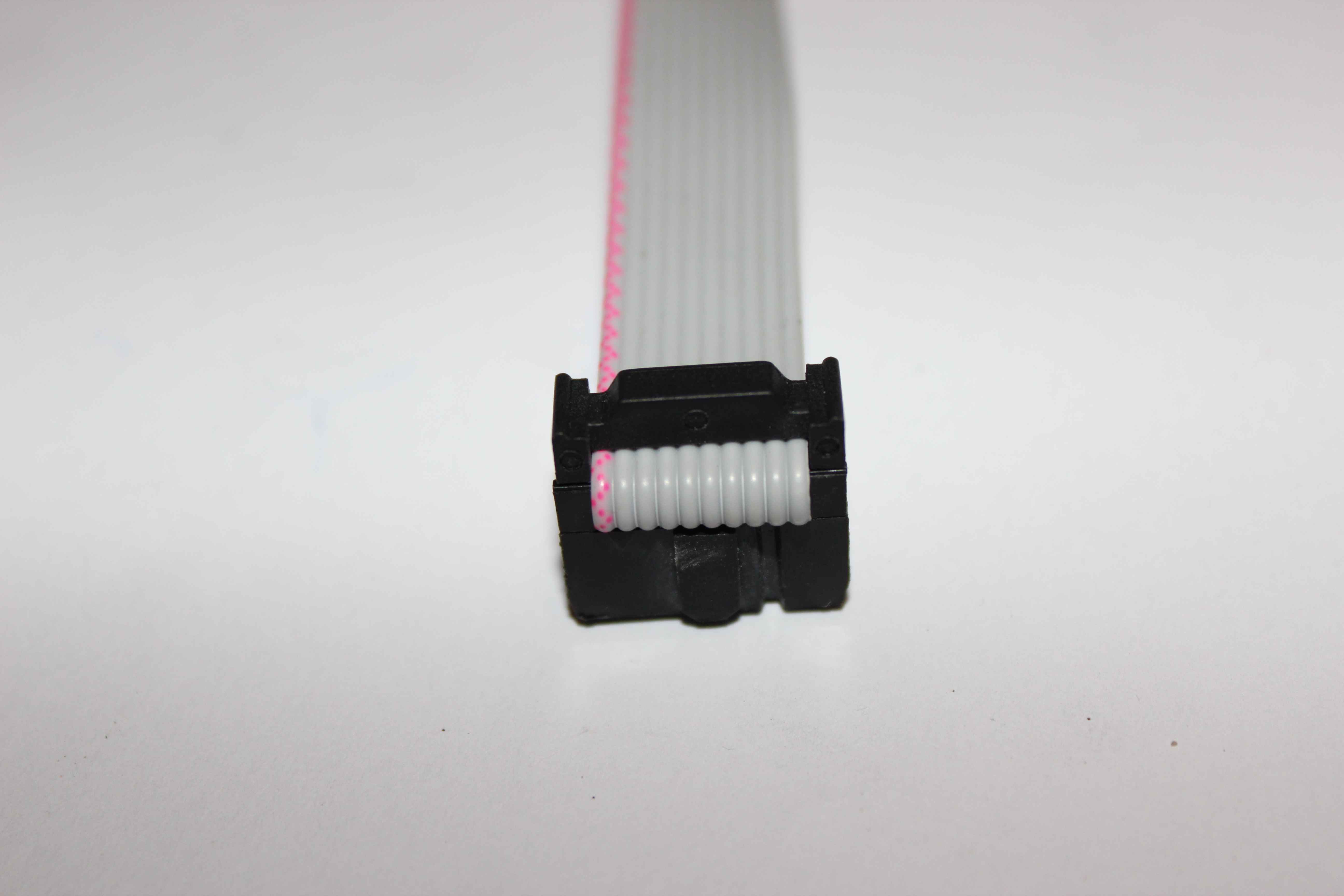
The flat cable wires should be cut to a length equal to the distance from the sensor to the controller, and tighten with IDC-10 pin socket at both ends.
One IDC-10 connector is connected to the controller and to the second terminal can be inserted directly by the sensors so that they are not shorted together.
The most convenient way to install controller from the measurement sensors close to planed furniture. This sensors could easily be hide from view and not exposed to mechanical damage , They should be located in areas where there is a whiff of air.
Such sensors can be painted with emulsion paint the color of the walls .
Installation of cans.
Count or sequential cans dependent on the number of switches , which we intend to use and the number of switches in one segment (box).
eHouse system using mono-stable switches ( Ring) . There are electrical switches on the market for bell / shutter with 1 ,2,4 switches in a can . For the use of 4 switches you need a total of 2 cans. Alternatively, you can apply the system switches containing up to 4 switches in one box. When the system switches can be connected backlight of switch ( 10 pin of flat cable – VCC).
Number of cans and installation method also depends on the use of infrared , In this case, since infrared receiver and / or transmitter must “see” external devices you must ensure transparency for IR. Alternatively, in the case of hidden drivers, you can move the receiver and infrared transmitter outside the can.