Evaluation – Demonstration module of eHouse Ethernet smart home
Smart Home eHouse Building management system is advanced electronic home , with implemented many algorithms , that operate independently of each other.
Testing and Debugging behavior of drivers is much easier “on the desk” than after installation in walls.
Demonstration / Evaluation Board should therefore be the first tool to design and test the installation and configuration of eHouse smart home system, at the stage of design automation control.
eHouse4Ethernet Smart home demonstration module allows testing controllers on your desk without having much more time-consuming installation at home.
The use of evaluation unit allows you to overturn myths and assumptions about the real possibility and algorithms in the system close to the target environment.
Evaluation Module allows testing all Ethernet controllers:
- CommManager
- LevelManager
- EthernetRoomManager
- EthernetHeatManager
- other large-scale Ethernet based controllers on the board CommManager / LevelManager
- other medium-sized Ethernet drivers based on plate EthernetRoomManager
Allows direct connection of all input and output signals to the module :
- display output states on the connected LEDs
- connected analog sensors
- lighting – phototransistor visible light
- temperature – LM335 , MCP9700
- contains 14 switches connected to the digital inputs
- display dimmer level by connected LEDs
- IR receiver to control EthernetRoomManager
- IR emitter to control external audio video equipment
In addition, the demo module gives possibility to test all Ethernet controllers and its hardware resources:
- digital inputs
- digital outputs
- measuring inputs – Analog transmitters – digital
- PWM dimmers
- IR transmitter
- IR receiver
In case of doubt whether the controller is OK , it is possible to run the same software of test module for possible damage.
In time, a part of the evaluation module , allows you to determine if any problems are due to:
- smart home automation algorithms
- damage
- misconfiguration of the module
- error or damage of installations
- damage to the switch , sensor , dimmer , relay
Connections of demo – evaluation module :
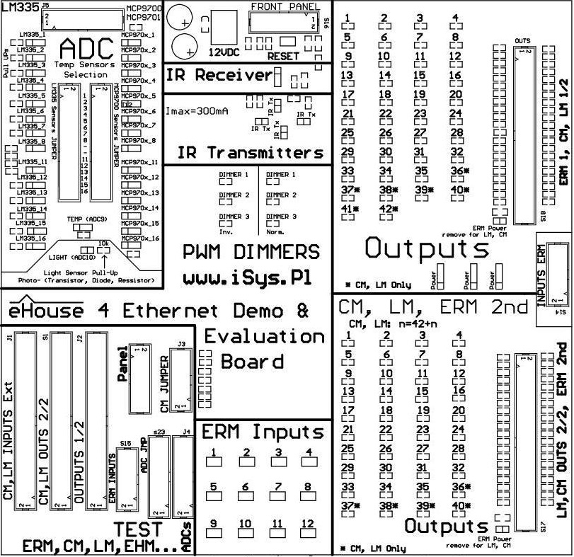
Demonstration module has several sections to test control algorithms, functionality and configuration :
- 2 outputs Sections “Outputs” enabling simultaneous testing of two medium-sized controllers, one or large
- “ADC” – sensors to evaluate all analog/digital converter inputs
- “Inputs” – digital inputs
- “IR Transmitter” – InfraRed diodes
- ” IR Receiver ” – InfraRed receiver
- ” Dimmers ” – PWM dimmers normal and inverted
Section of the digital outputs – OUTPUTS
It has installed LEDs connected to each digital output of any controller.
Activation of the output driver illuminates the LED connected to a particular output.
Sections have respectively 42 and 40 outputs for testing of all types of Ethernet controllers .
Section of the digital inputs – INPUTS
It has installed “push button” switches type connected to each input ( max 12), shorting them to ground when you press the key.
Connector inputs are compatible with standard ERM .
Section dimmers – Dimmers
Each controller has 3 DC PWM dimmers without power driver. The output can directly control the transmitting diode driver insulator power in two ways:
- normal – LED located between the output of the dimmer ( anode ) and ground 0V ( cathode )
- Inverted (INV) – LED located between the output of the dimmer ( cathode ) and a positive voltage of controller – 3.3V ( anode )
LEDs connected to dimmers show illumination level.
Sections transmitter and IR receiver – IR
- IR receiver section includes a receiver circuit infrared signals used for auto – test or control ERM standard IR remote control for Sony
- IR transmitter section includes IR emitters ( LEDs emitting in the infrared ) with current limiting resistors to a safe value for the driver and LEDs . It is used to test the transmission of control signals for Audio/Video equipment – from ERM controller
Analog/digital converters inputs – ADC Section
This section contains a set of analog sensors can switch the input to the sensor :
- up to 15 MCP9700A or MCP9700A sensors
- up to 14 sensors LM335 with Pull Up resistors to the supply voltage of controller – 3.3V
- light sensor – phototransistor
It also contains a set of “jumpers” to choose analog sensor type for each input for sensors LM335 and MCP970x .
For more information about eHouse Ethernet controllers : Smart Home – Room Controller
Smart apartment flat
Smart home – drives, servos
– Roller , gateway, gate , shade awnings controller with Alarm with SMS notification