eHouse Smart Home making professional mini – switchboard for single segment installation (Room)
Smart Home eHouse can be installed independently by investors and professional installers.
To make installation safe, professional, secure, trouble-free for years , we produced dedicated relay modules for the system eHouse1 , Ethernet eHouse controllers and other versions of the system. Regardless of whether it performs amateur – hobbyist , a child or a professional installation looks the same professional and can be done equally well with considerable savings on professional installers of building automation systems.
Self-installation of eHouse home automation allows savings about 2-3 times the cost of installation by a professional service , so it is worth fighting for .
In addition, DIY installation requires a minimum gain knowledge about the system, so it not “black box” any longer.
Amateur, hobbyist, IT geek who install the system yourself gaining the knowledge needed not only for installation, but also the possible maintenance.
So far, by making the mini switchboard in accordance with Article smart home room switchboard .
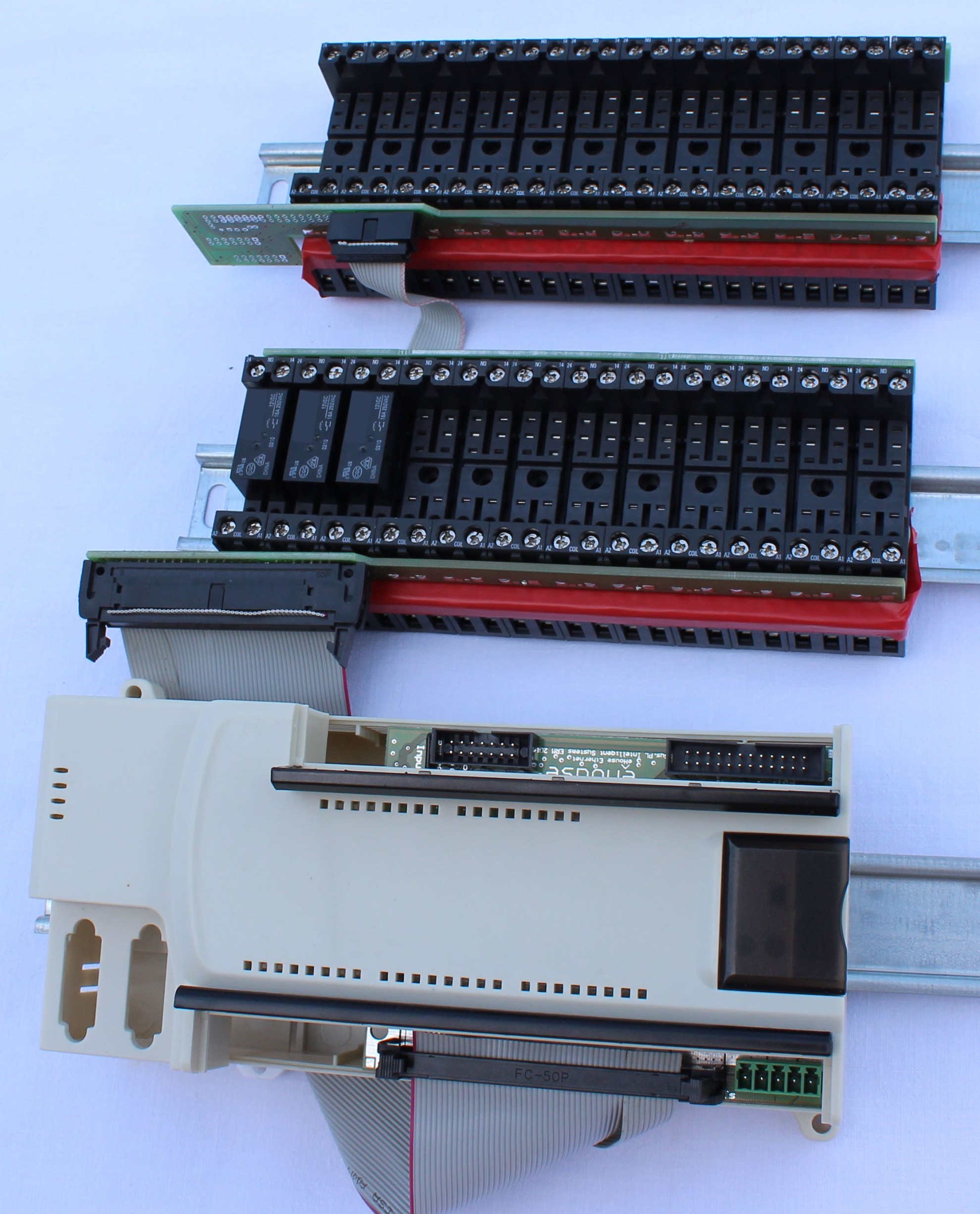
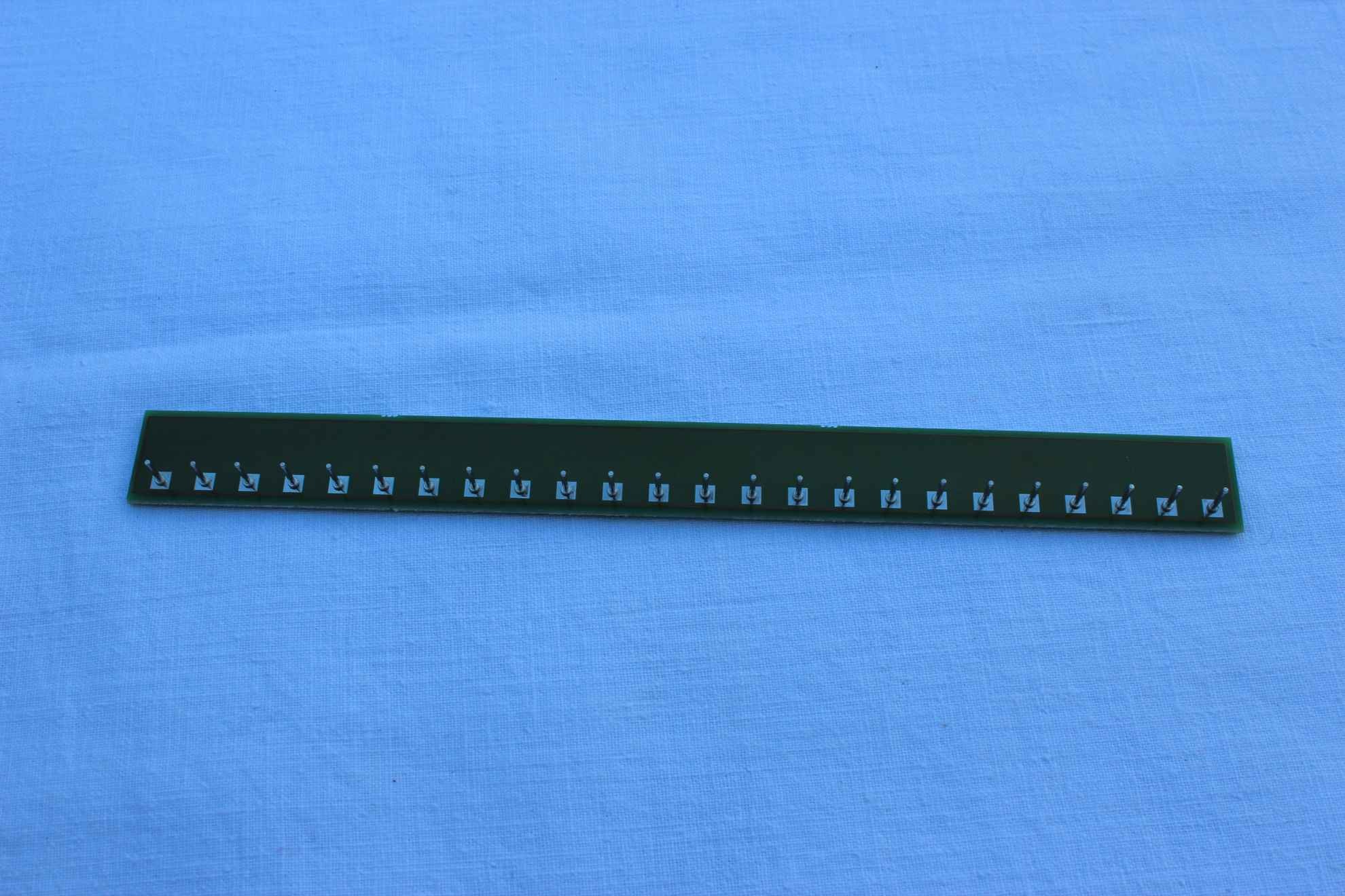
Recently we issued relay modules for installation on DIN rail implement whole set of low voltage connection (between the controller and relay coils) and the armature of the relay contacts .
This reduces installation time of switchboard from above 3 hours to approximately 0.5 hours (not counting wiring for electrical and electronic equipment {230V wires}) .
Relay modules are designed for 12 relays especially dedicated to eHouse system (230V/16A), the use of other types of relays for the relay modules is not possible because, each relay type differs in size , dimensions , distribution and use of the relay terminals differing in dimensions of up to one millimeter will change the distance of 1.2cm on the last relay.
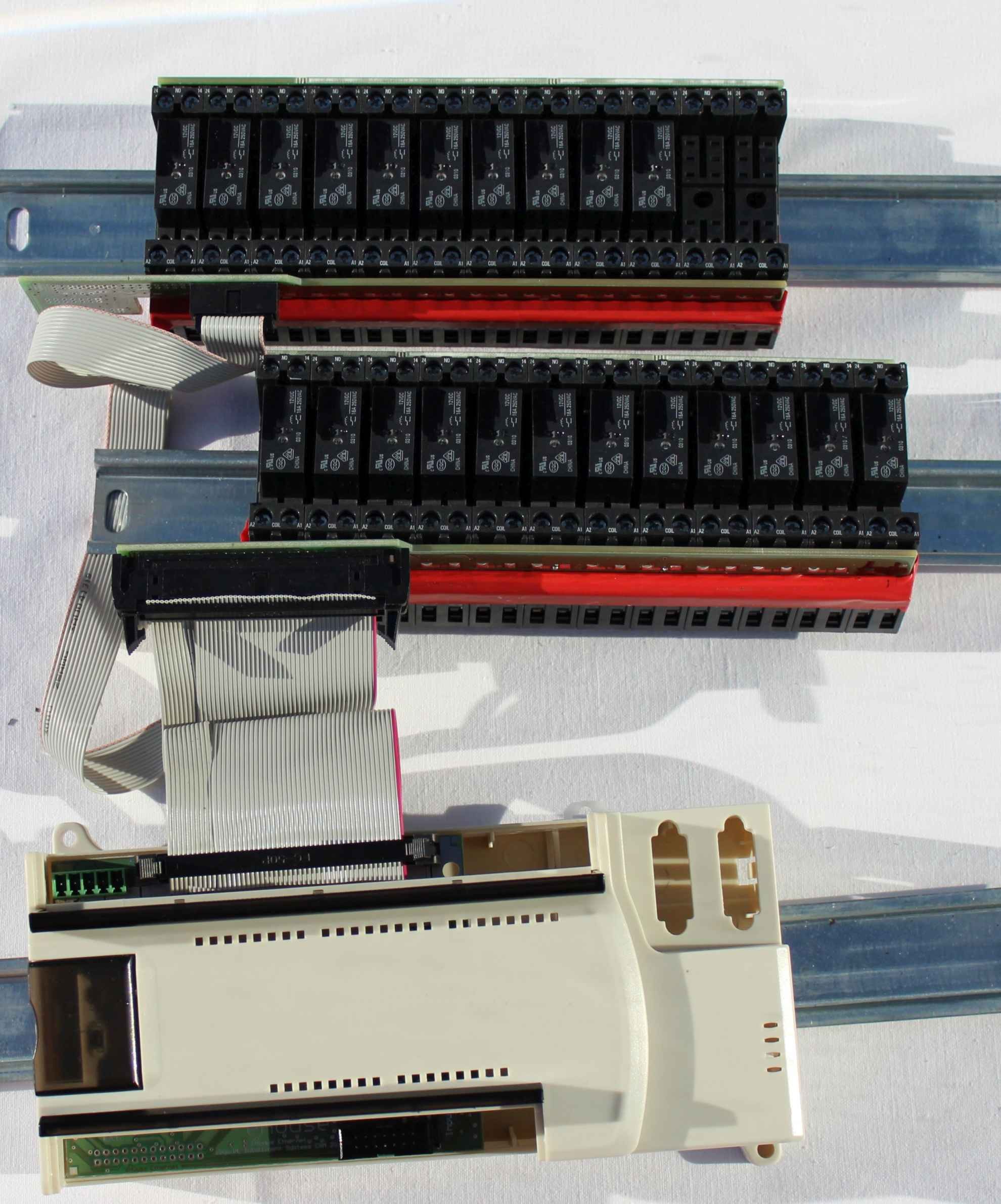
There are three types of modules:
- basic relay module – connector to connect directly to the driver ( Smart House eHouse Ethernet Room Controller ) IDC-50 (default) or 40 ( RoomManager ) – output 1..12
- Extension relay module – connector for connection to the basic module IDC-14 O13..24 for the lower slot of the basic module , and outputs 25..32 for the top slot in the base module )
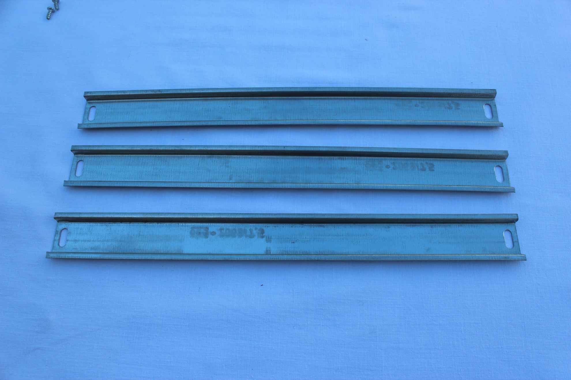
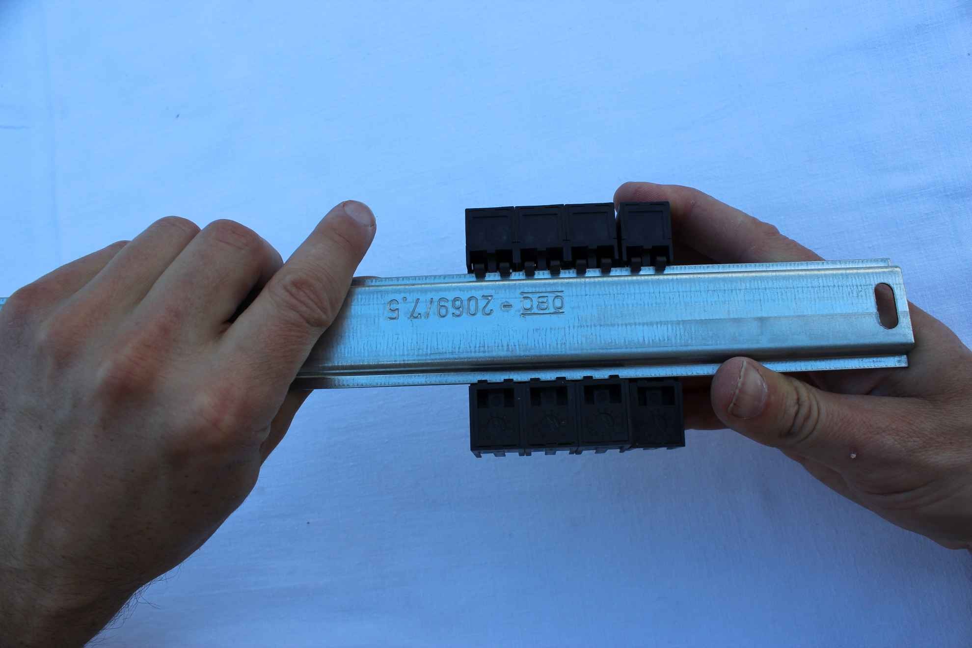
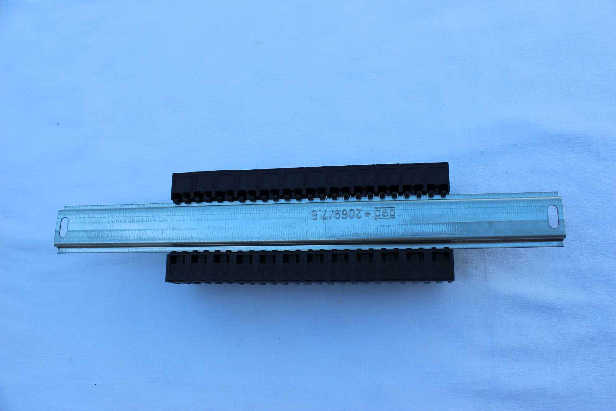
- COMMON rail to connect relay contacts to not have to tighten the cable
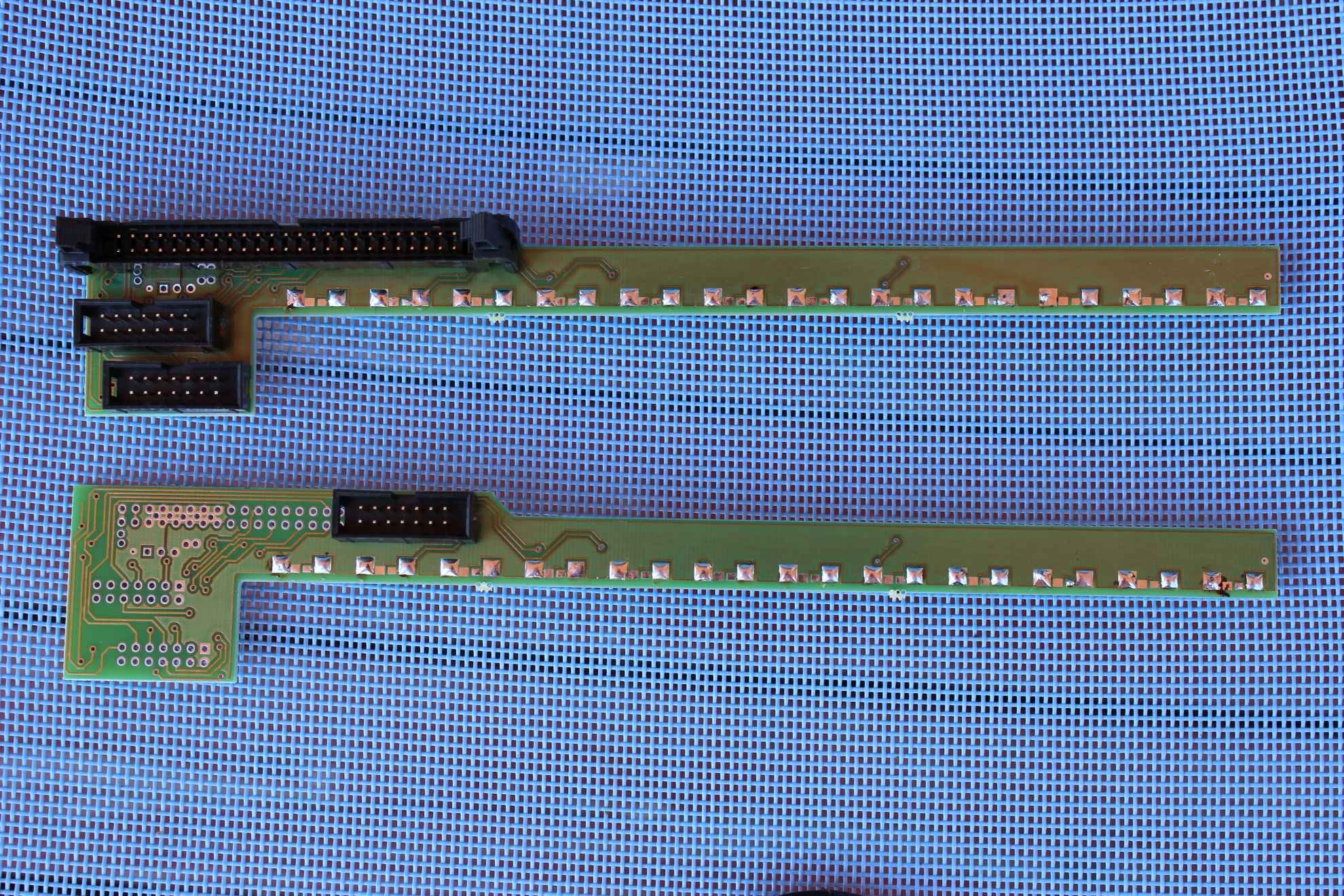
Default modules are manufactured in accordance with the above images , however, in the case of larger quantities ( for particular applications or drivers (e.g. . RM eHouse 1 ) modules can be ordered with a different set of connectors or without ( eg IDC – 40 , IDC – 50 with or without ejector ) . This is important if, for example will be used in places with very limited space and every centimeter counts ( as boats, yachts, etc. ).
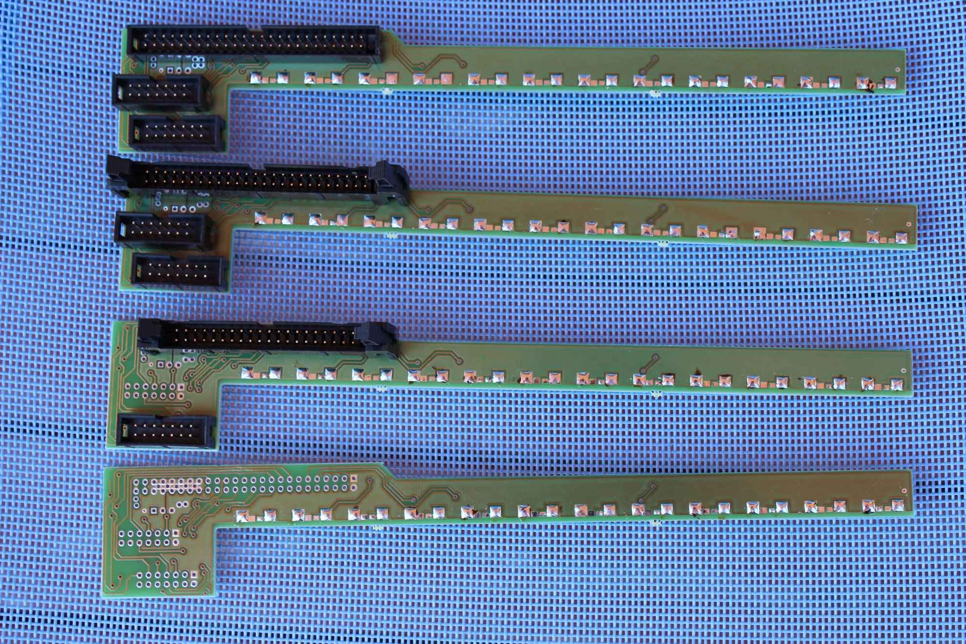
- 1 basic module allows you to connect 12 relays
- 1 basic module + 1 Enhancement relay respectively connected to allow the use of up to 24 relays .
- 1 basic module + 2 relay expansion modules respectively connected to allow the use of up to 32 relays ( eg for CommManager or another driver with more outputs) .
In the event that we are forced to use a different type of relay (multiphase, for inductive loads), it should be installed at the end , not using the relay module. In that case, use a longer DIN rail .
These modules are designed so that if you need less relays on the rail it can be cut off at the narrowest point of the circuit board ( shears for cutting sheet metal – must ensure that there are no short circuits and protect insulating varnish) .
For comparison method for mounting ( patch ) switchboard using only the cables is described in the article
Smart House eHouse – amateur performance mini substation It is tedious , time-consuming , sensitive to errors , inaccurate installation and easy to be damaged while perform maintanance.
When choosing a box for mini switchboard must take into account many factors:
- whether it be a switchboard for comfort version of eHouse distributed in room, or a single switchboard in the facility ( eg . holiday-cottage , boat , yacht )
- whether we are going to mount the controller inside switchboard together with relays
- how many relays we are going to use, and whether it is necessary to use other than dedicated relays for eHouse
- if we intend to use fuses in the same box ( especially if one switchgear in the plant ( recreational cottages , yachts , etc. )
- we intend to use mini separately in rooms or one central switchboard
Depending on the answers to the above issues we have several cases :
- switching with a minimum width equal to the DIN rail 12 modules ( relay / fuse )
- number of rows of two or more
sample box for mini switchboard : 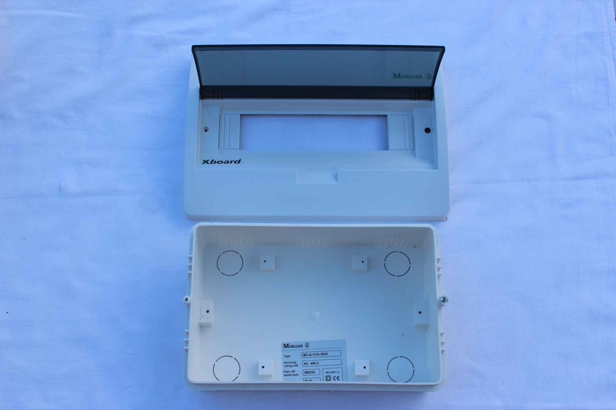 Commercially available variants containing 12 , 18 , 24 modules in a row . Number of rows 1 , 2 , 3 .
You can use basically any modular switchboard with DIN rail size which is necessary for example .
Before you buy separately , which we like ( in larger quantities), should assemble one piece in order to check whether all the elements fit without problems.
We do not recommend to buy very small switchboard (about densely packed rails and a small free space in the middle).
It will greatly complicate the installation of the flex cables 230V in large quantities and increase the installation time several times.
Also be aware of a possible revision, service, maintenance. At very tightly stacked 230V lines there is a risk pull cord ( from the fixing screw ) when moving a different cable , etc..
Please also note , that both wires are switching 230V and low voltage (12V ) for the relays inductors and accidental short circuit to 230V will cause permanent damage to the controller or the entire system if the segments are not separated from each other.
Profit at the lower surface of the box is apparent , the mini switchboard installed in the premises are planning to place for small furniture where a few centimeters difference is not ” positive ” significance .
Before starting any work on preparing a workshop :
- large table 1/2m
- cover the table with light towel or a thick cloth in a single color. So you do not scratch the table or front of the switchboard and not lose parts, screws .
- a small low-speed electro-screwdriver for fitting computers with a long tip (small star size 1) – screw bases relays
- ordinary electro-screwdriver for assembly of larger components – low speed
- a set of manual screwdrivers of various sizes
- IDC crimper
- IDC flat tape – 14 and IDC – 50 and connectors
- varnish insulated wire , screws and components for low voltage
- electrical insulating tape 2cm and 5cm width
Implementation of several switchboard takes a few hours and do it “on the knee” will certainly complicate and lengthen work, will be far from the enjoyment job.
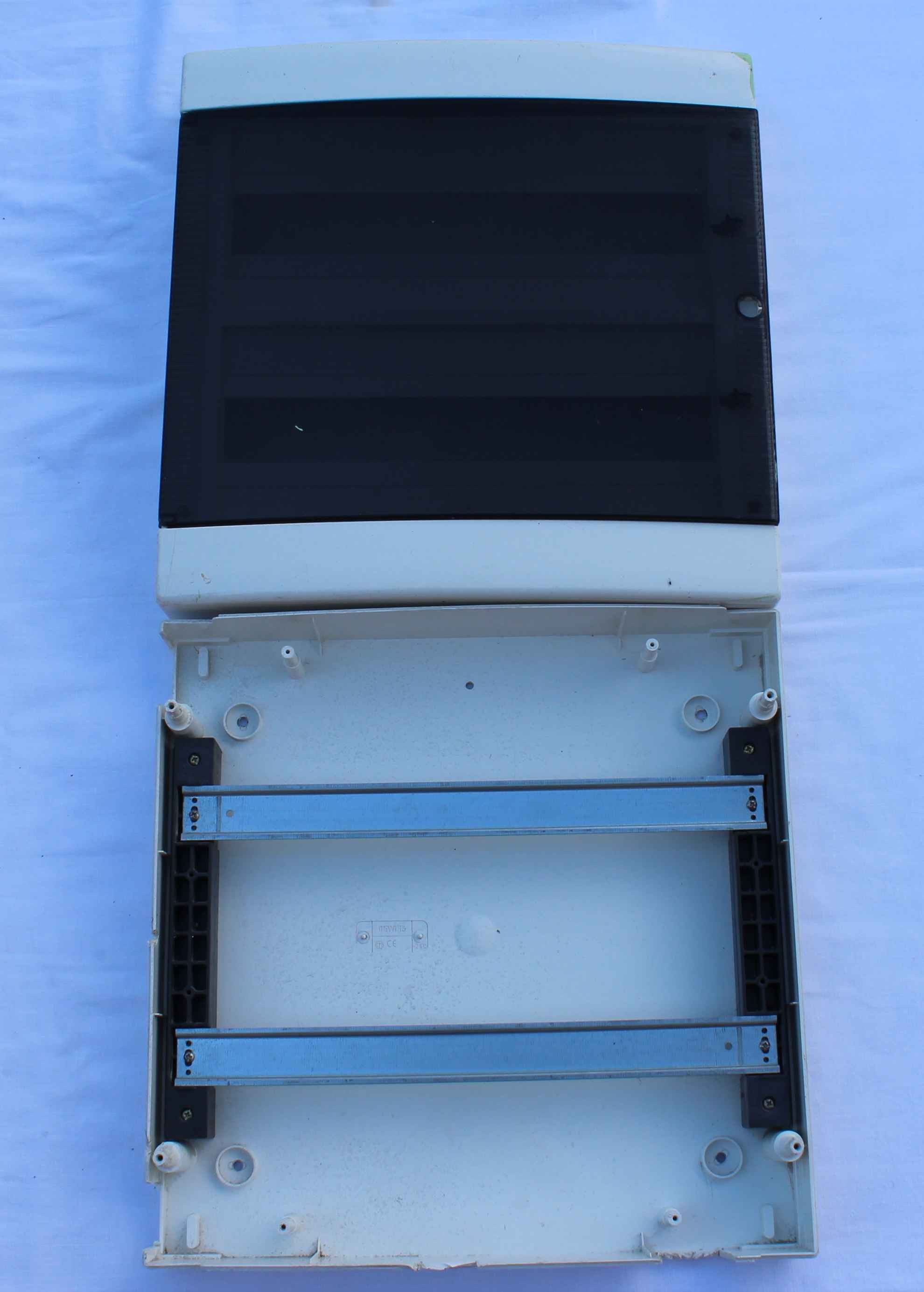
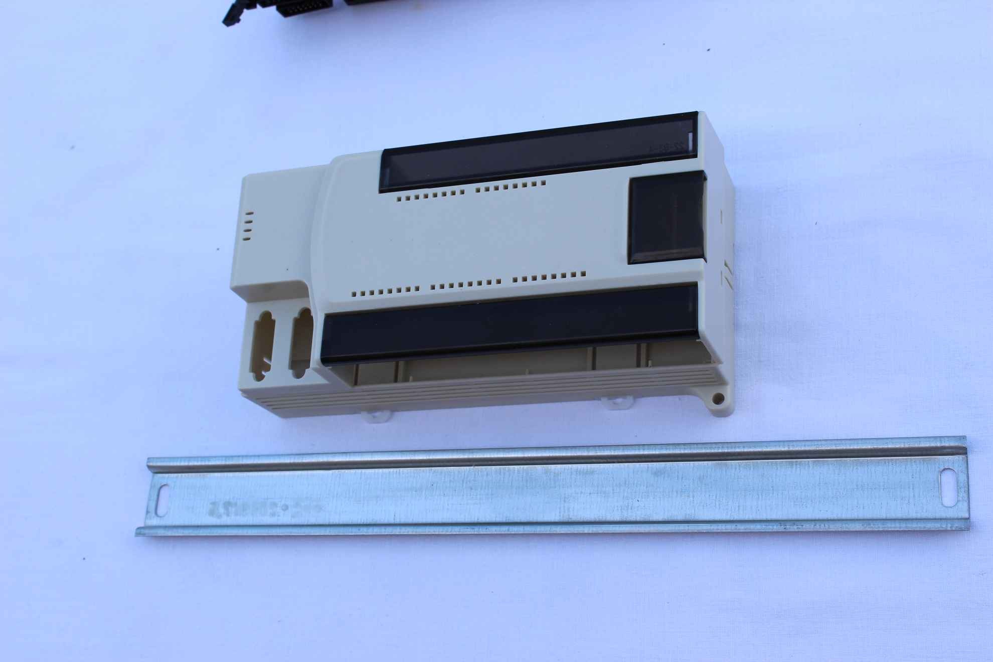
If you have decided already and purchased target switchboard – to install it:
- unscrew the housing front
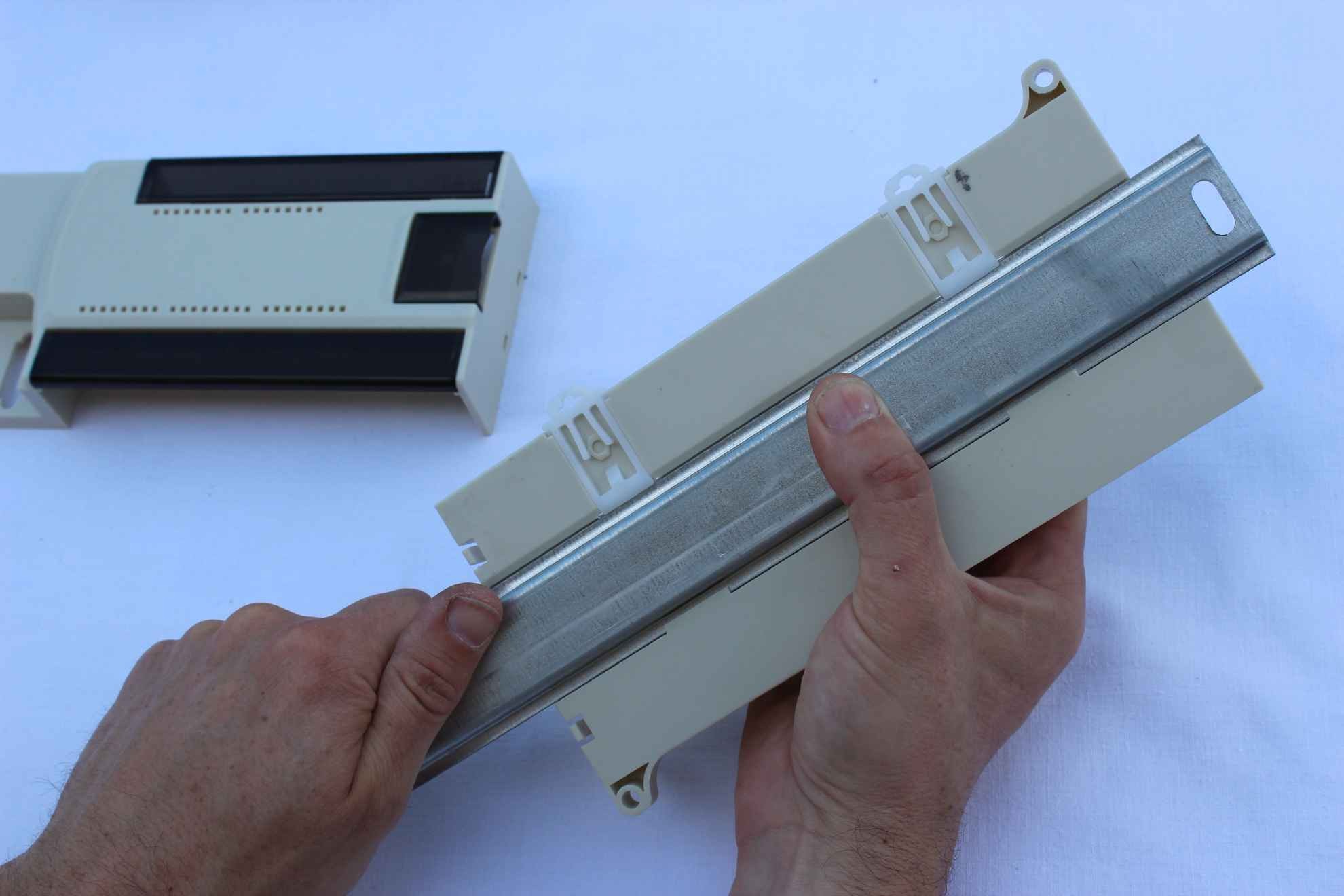
- remove the DIN rail – by unscrewing the two screws at the ends
- each take cover in a safe place not to damage – work only on empty DIN rails
If you can not find the switchboard , You can install a set of relays and accessories on an empty DIN rail and check in the store before buying, which box best suits us.
You can also eject the DIN rail and inserting a new box after purchase .
The following installation instructions present in the switchboard 3 row ( eg.for recreational cottage with fuses and other security and 12V power supply for DIN rail for driver and LED dimmers ) . Other variants of the switchgear can only be simpler.
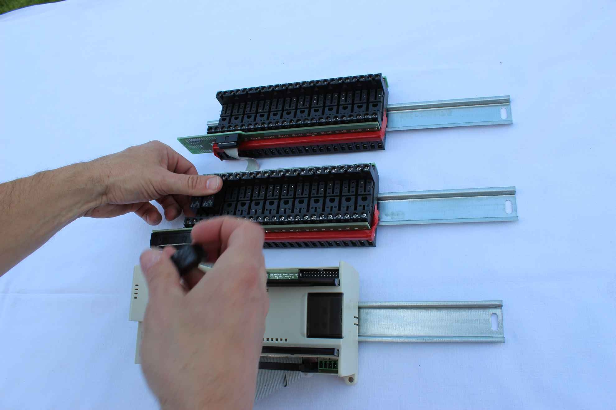
Supports switching relays used in eHouse allowing multiple assembly, replacement and removal of relay.
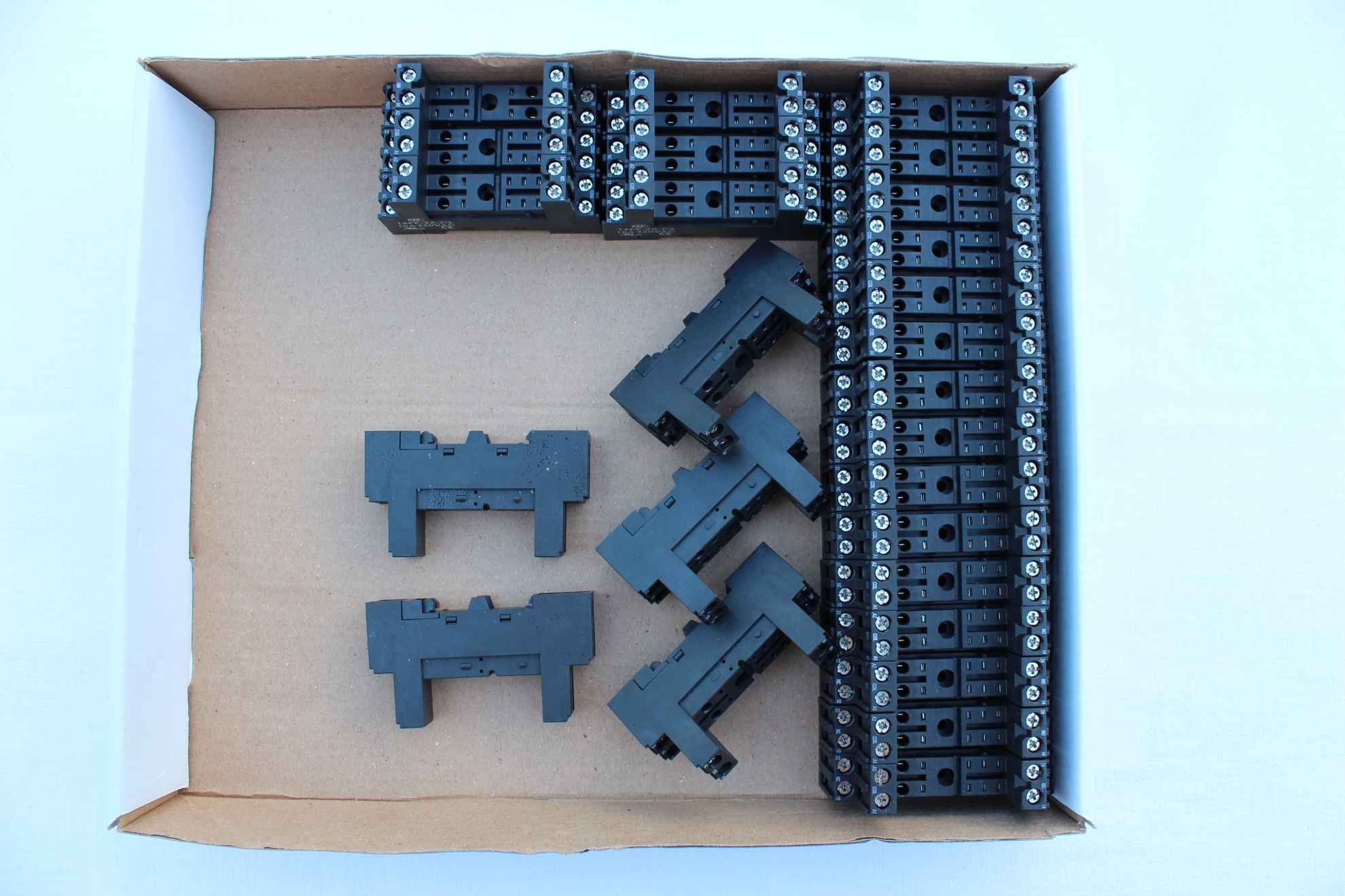
Relays used in eHouse switchboard 230V/16A inserted into the stands after the installation
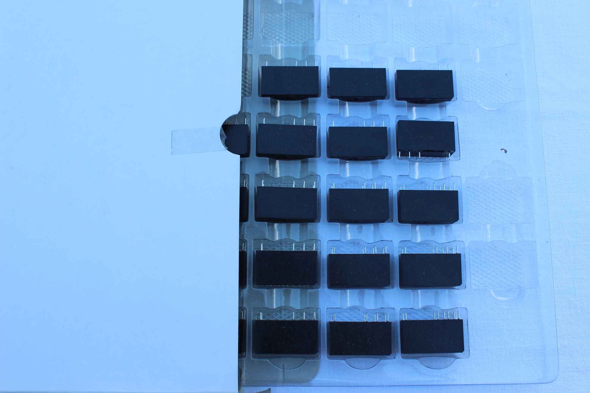
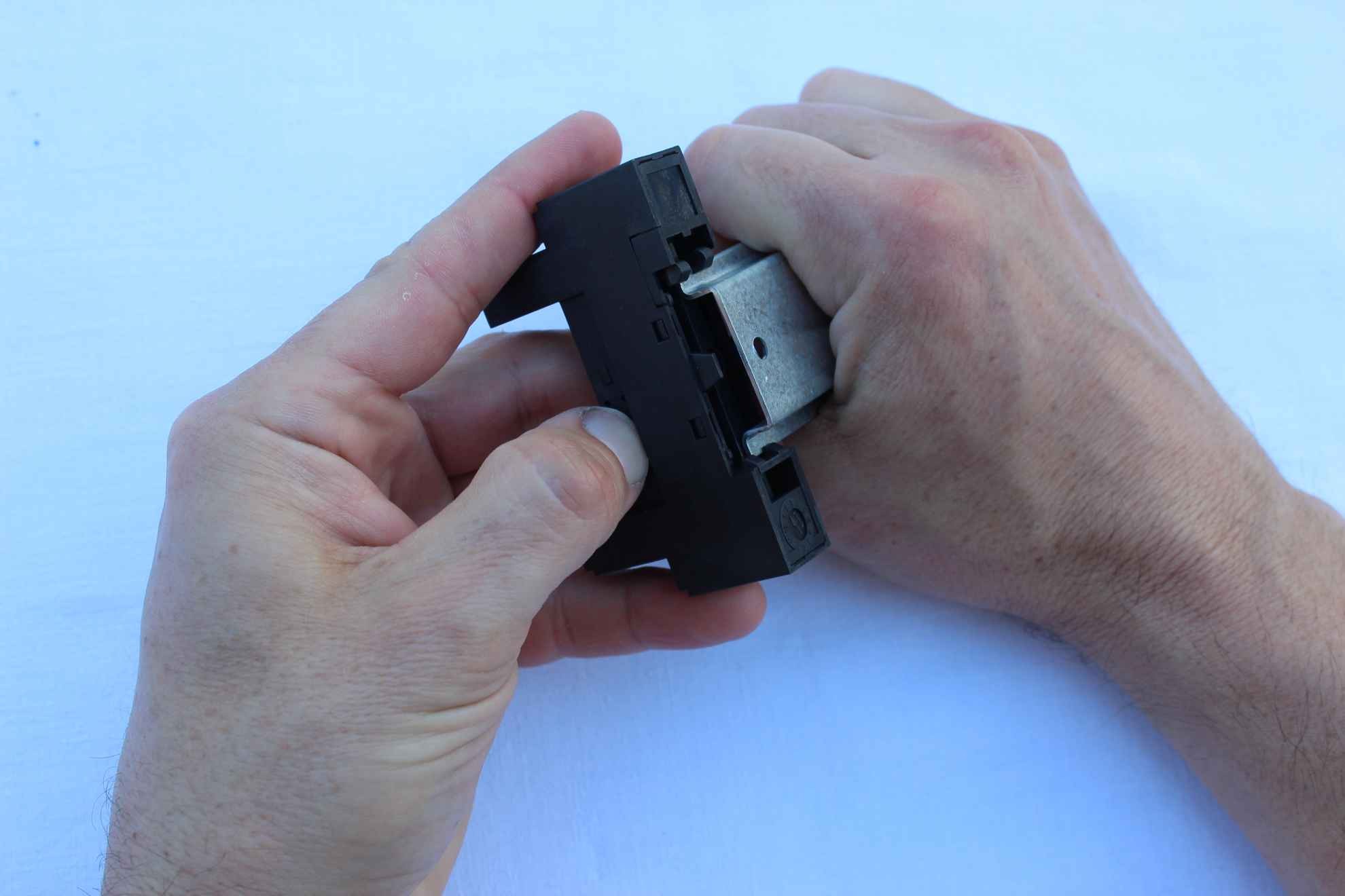
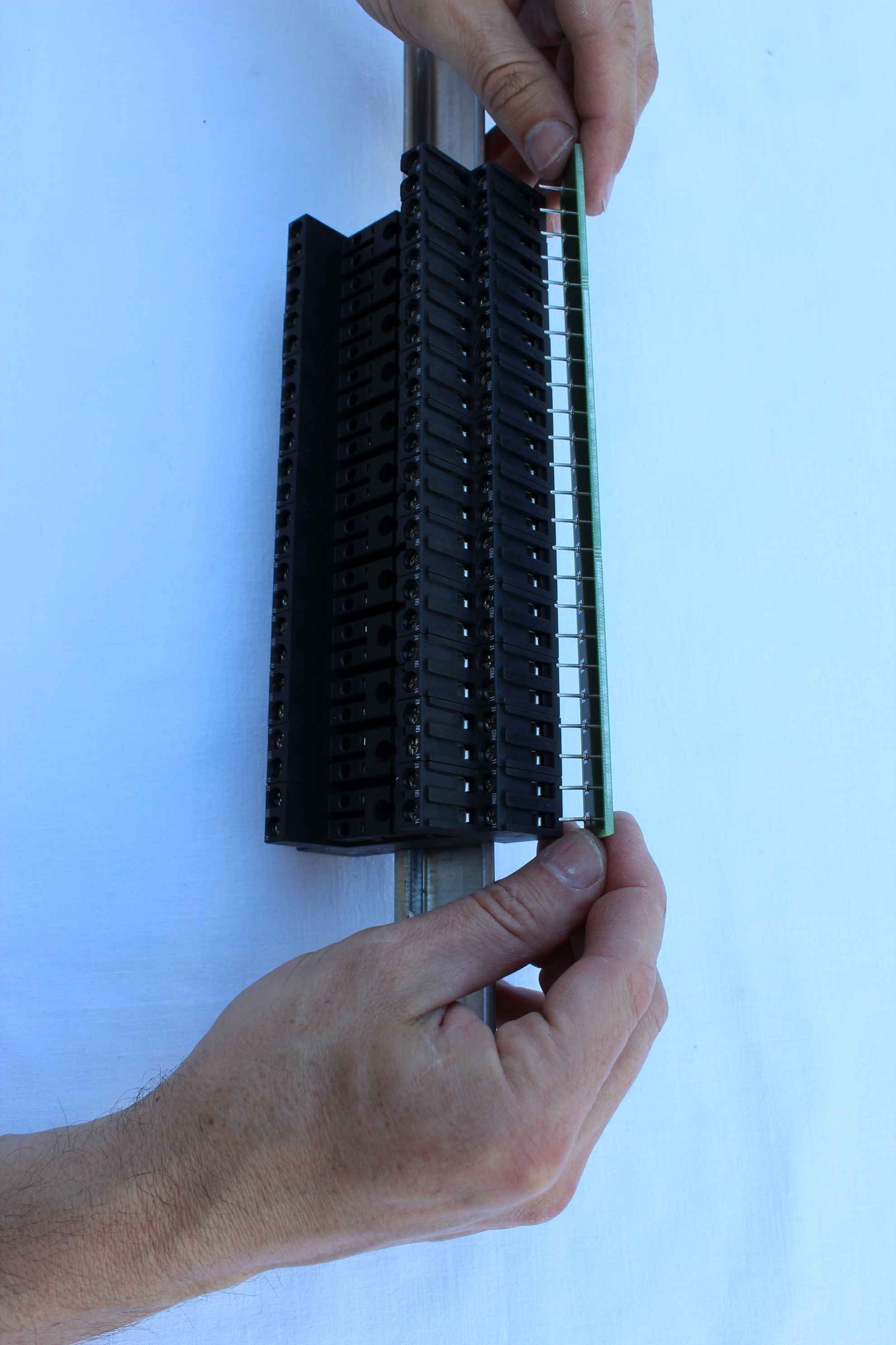
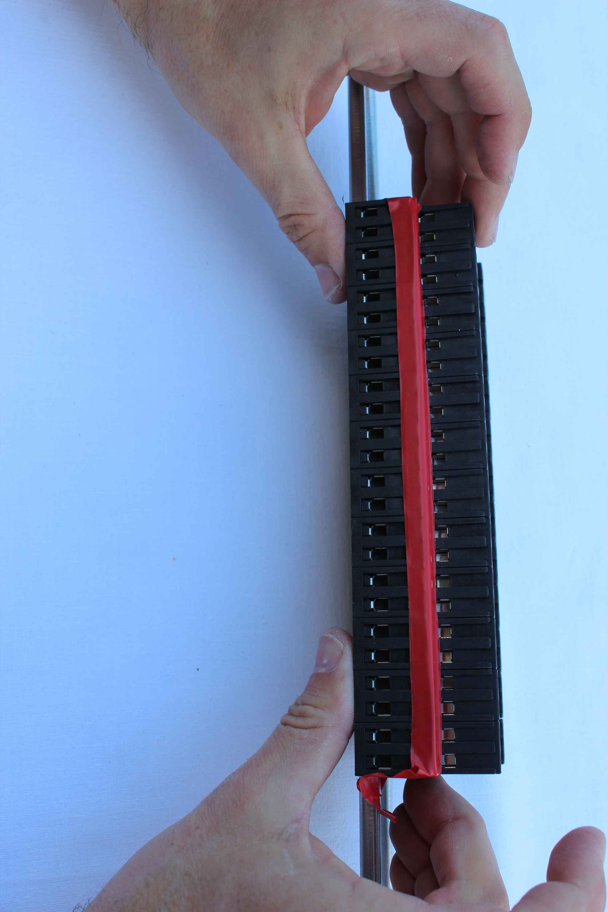
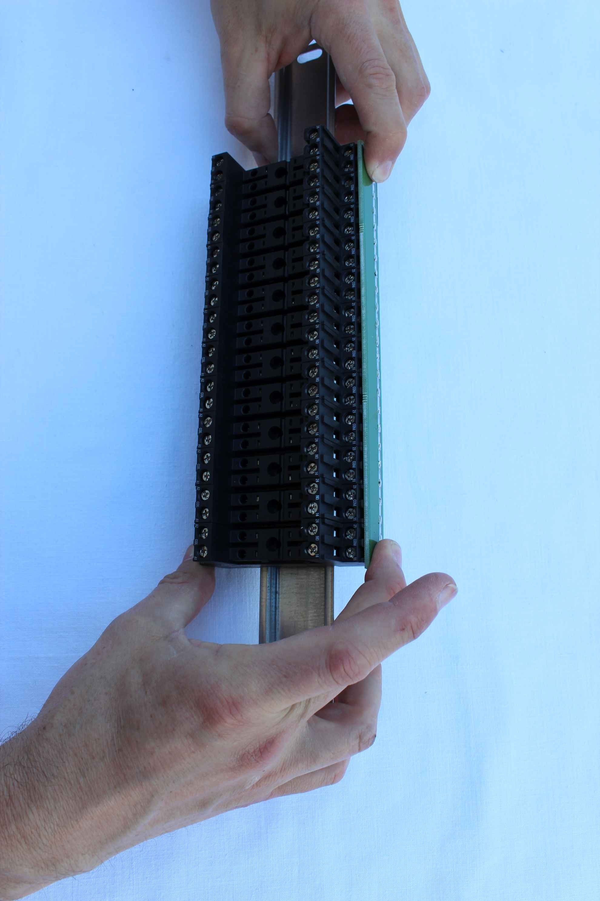
Application stands relays for DIN rail can be done in two ways: sliding from the side or by pressing the planned location .
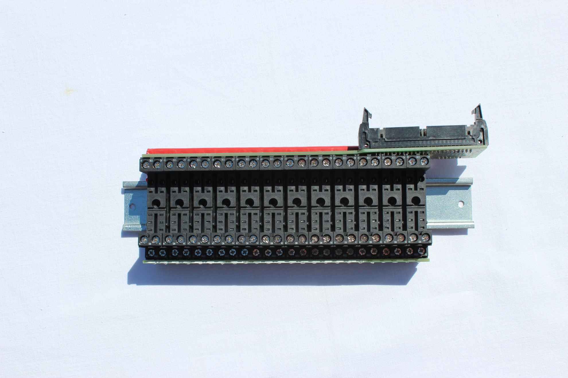
Set of 12 relays mounted on a DIN rail ( bottom view )
Relays ( and output drivers) should be divided into voltage receivers to simplify switching up and installation .
If all relays will turn single voltage ( single-phase ) does not need to do anything .
1 relay contact (COM – common) shorts to a single supply voltage ( eg . 230V ) .
Otherwise, you need to be divided into as many segments as there are different voltages .
With two voltages , one DIN rail relays can switch the device on one and the other another voltage . Alternatively, you can track NO scissors to cut the sheet to the desired length (this requires a thorough insulate and about 1 cm spacing between adjacent slats . This leads rail voltage 230V or other so all ” improvisations ” should be performed carefully and so as not to cause danger or later breakthrough for other voltages . All these steps are performed at your own risk Installer .
Unscrew ( loosen ) all screws marked on the relay ” COM ” (Joint labeled both 21 and 12) to obtain a wider opening appears for the insertion ends of the side rails sphincter .
Insert centered in the holes marked coasters “COM” .
The protruding pins of the module should be in line with all the measures of these screws.
Screw the mounting screws are made miniature screwdriver to hardware when set minimum speed and minimum tightening force. Then you can tighten the (sensitive ) manual screwdriver to turn the screws.
Tighten the last stand while pushing the first to be touching each other
At the end Tighten all screws with screws contact COM
Turn sideways and pre visually check that all screws are tightened ( see module below the hole or not) .
The next step is to insulate the unused relay contacts ( “NC” – normally closed) because then there will be access to them. At the beginning of the bolts should be tightened as far as screwdriver . The next step is to flood these screws to get the best coating thickness greater than or equal to 1mm .
Then seal with electrical insulation tape the screws ( marked ” NC ” on the relay cover ), with few inches spare of the tape stick to the sides of the stand .
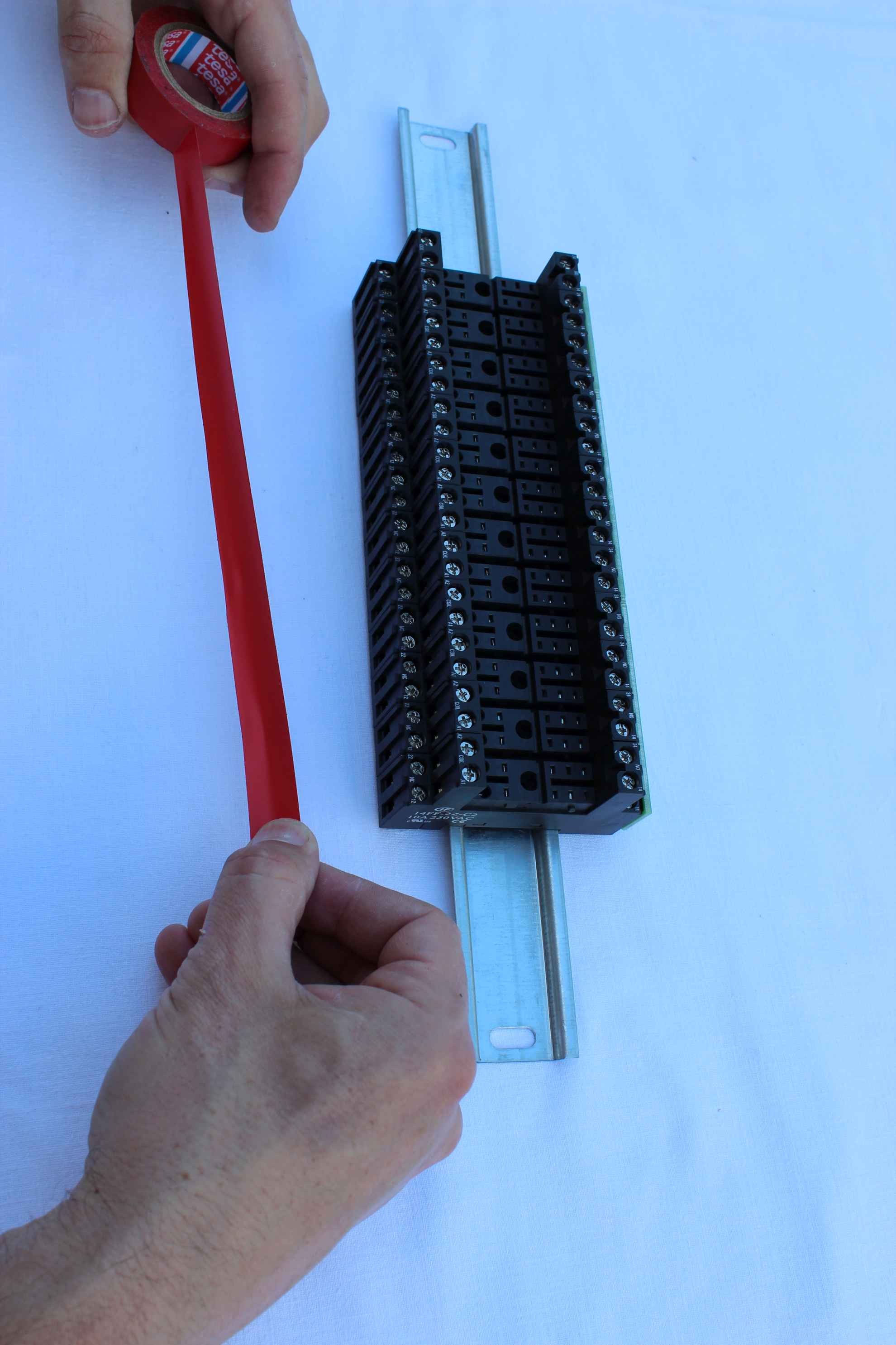

another layer
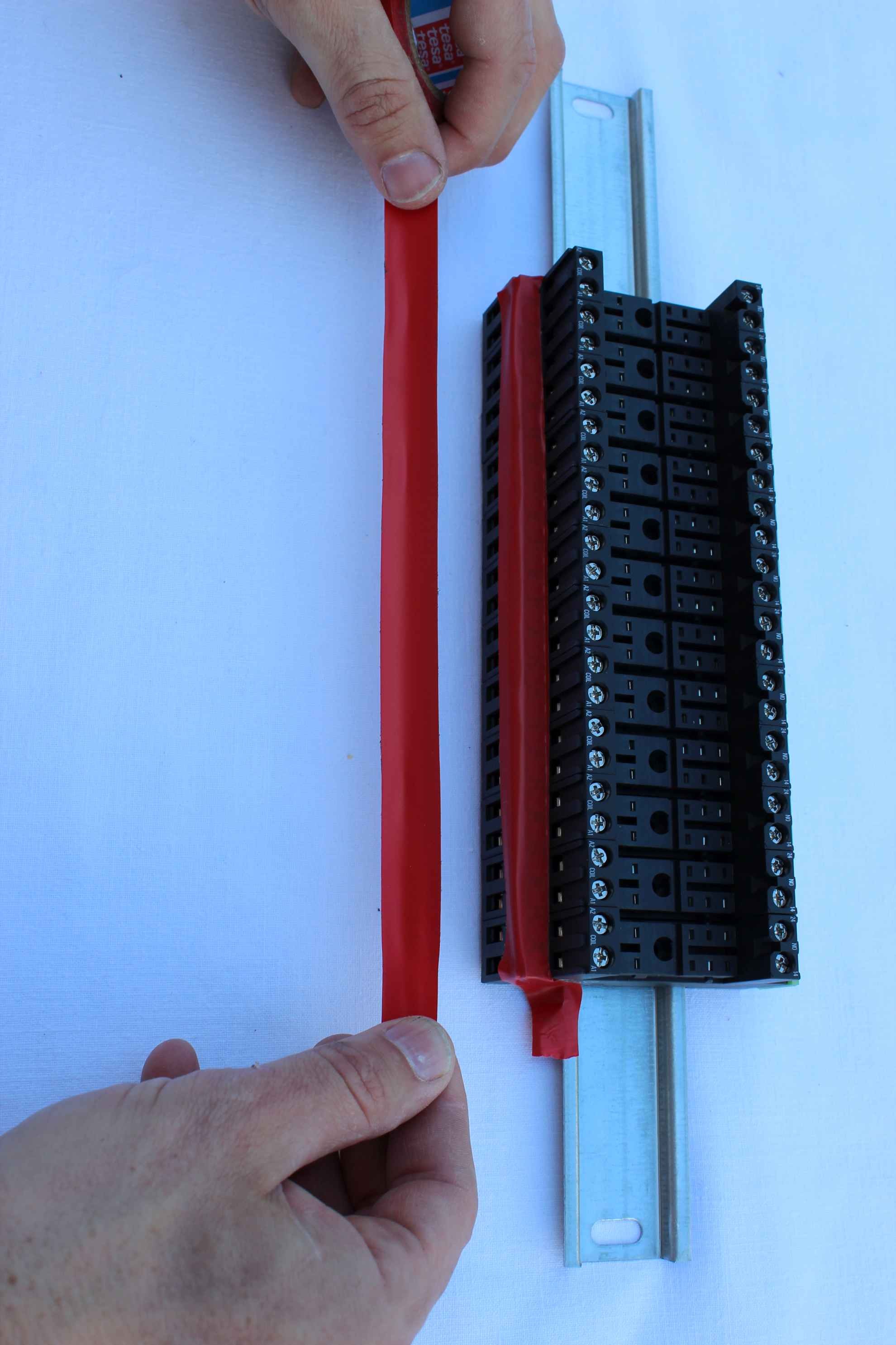
Insulating tape , carefully press firmly all over the place .
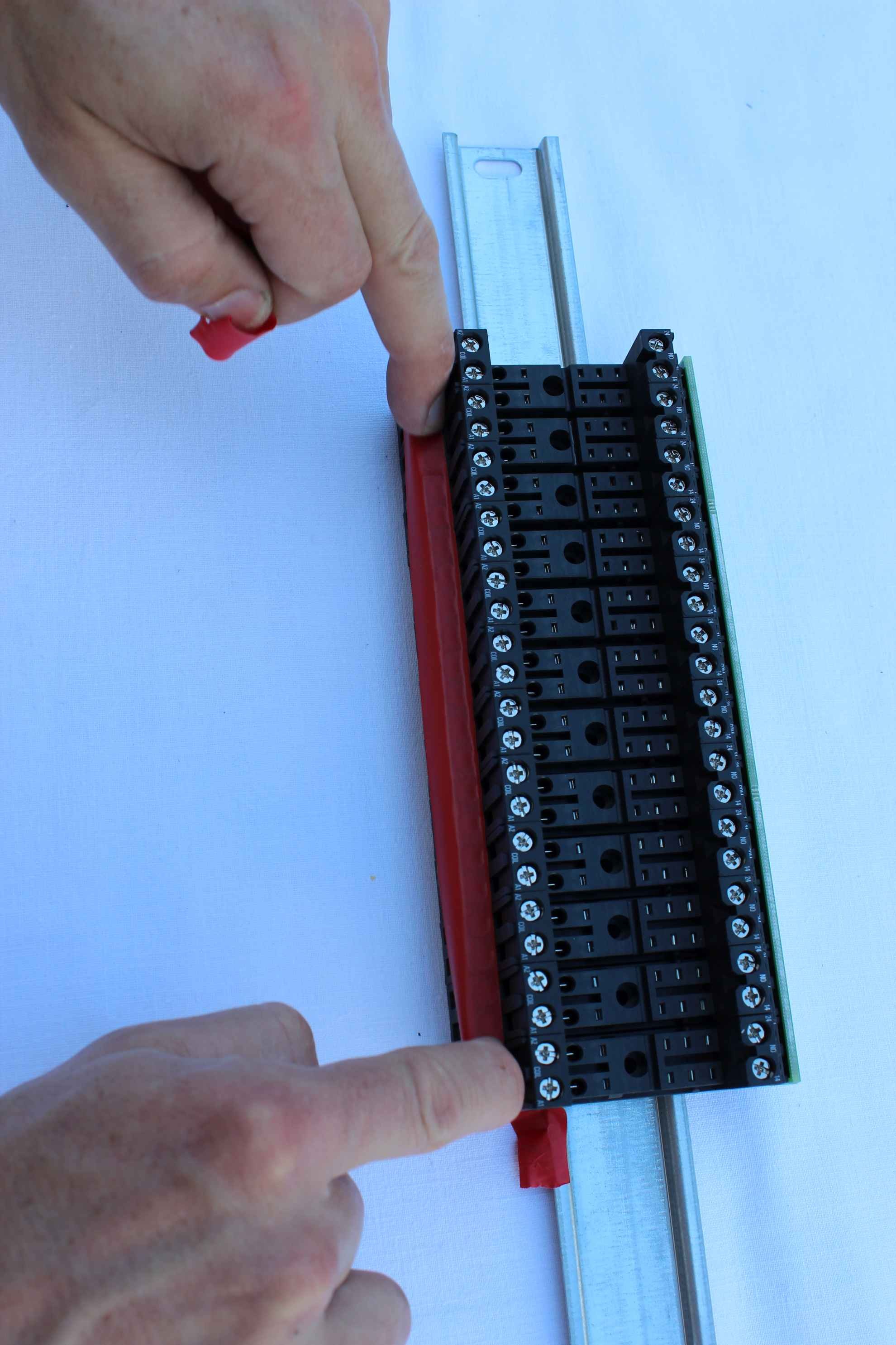
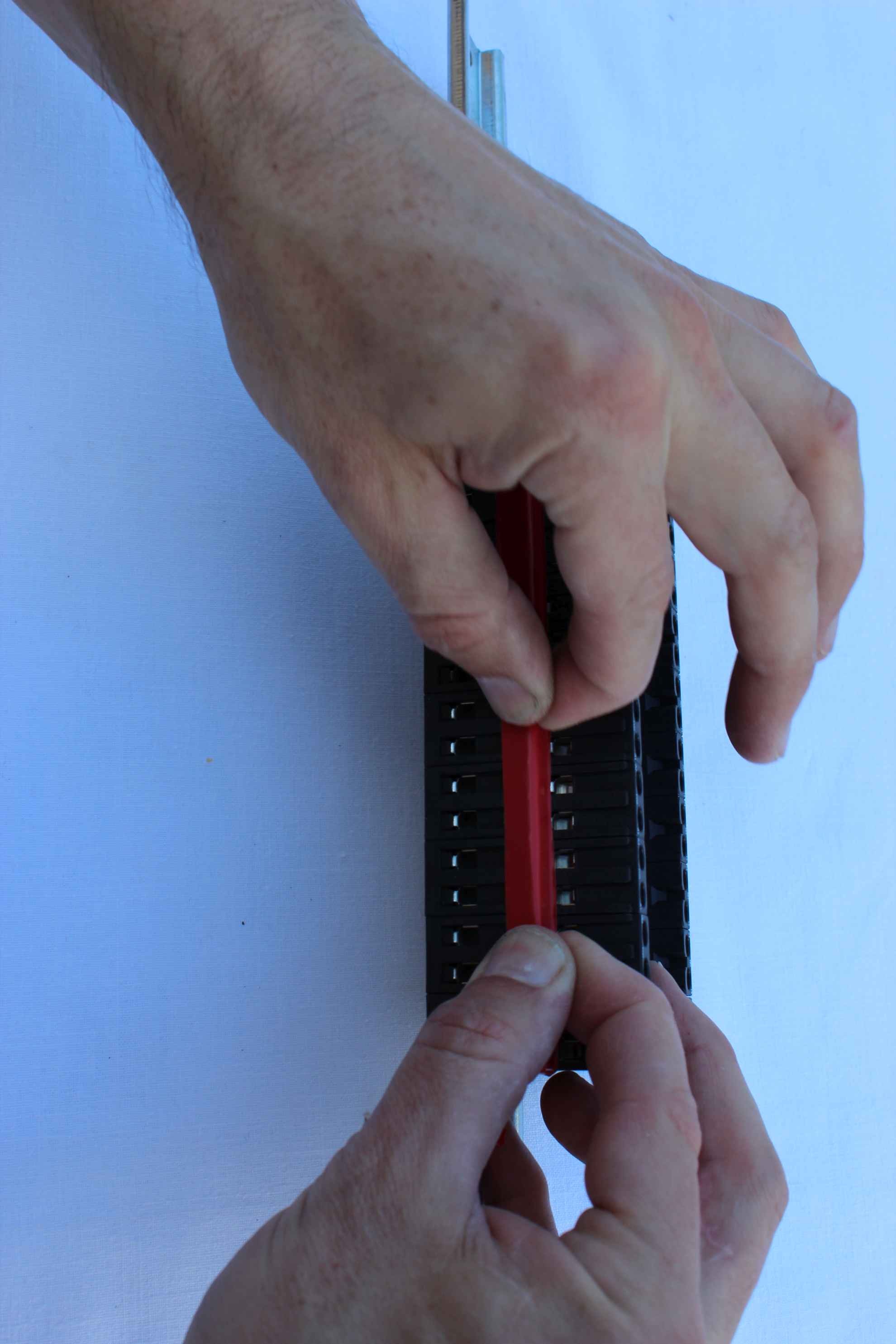
At the end of the duct tape sticking out of the side of the curl and paste an aside to the relays and push to not become detached itself through years of use.
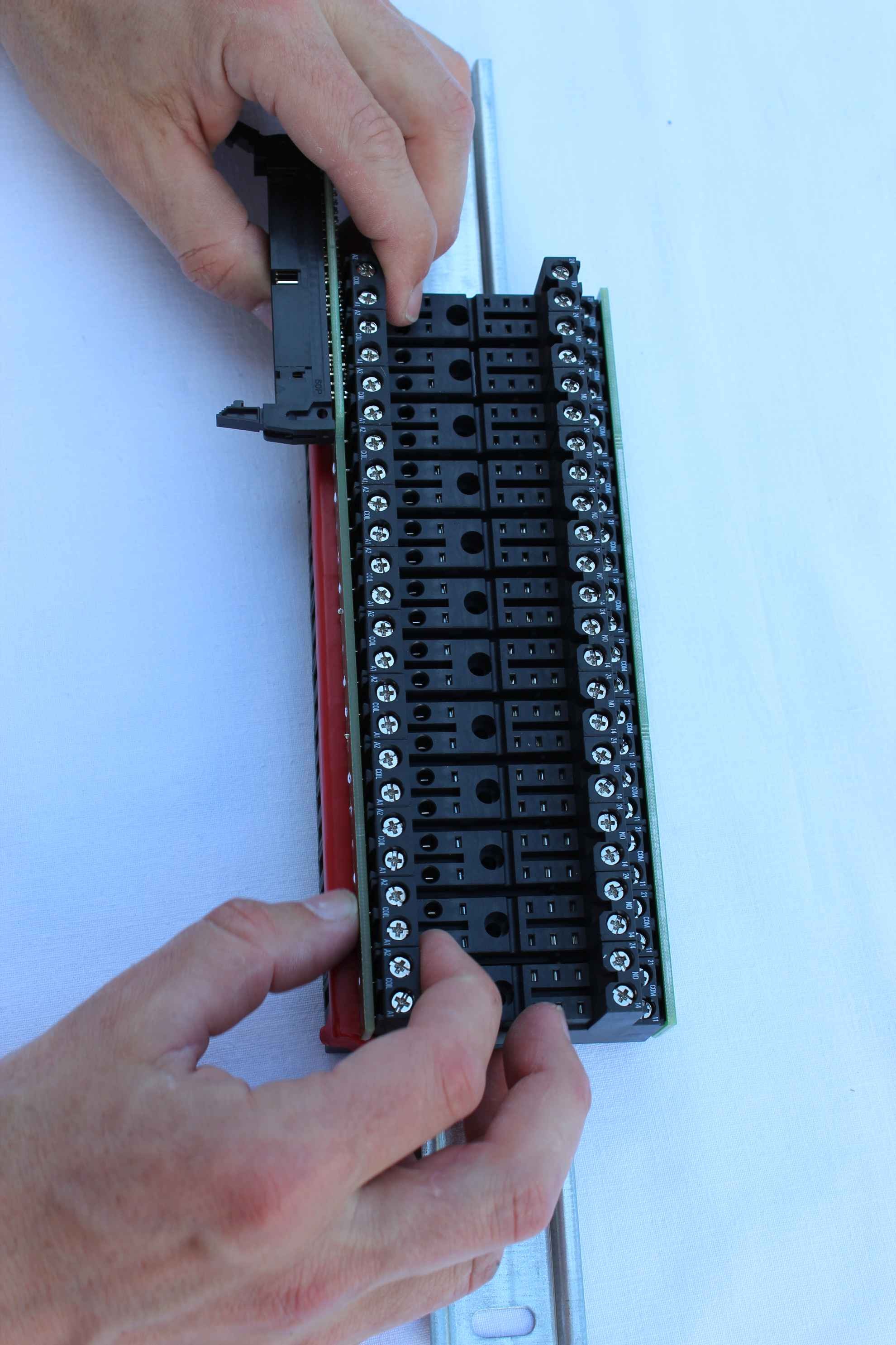
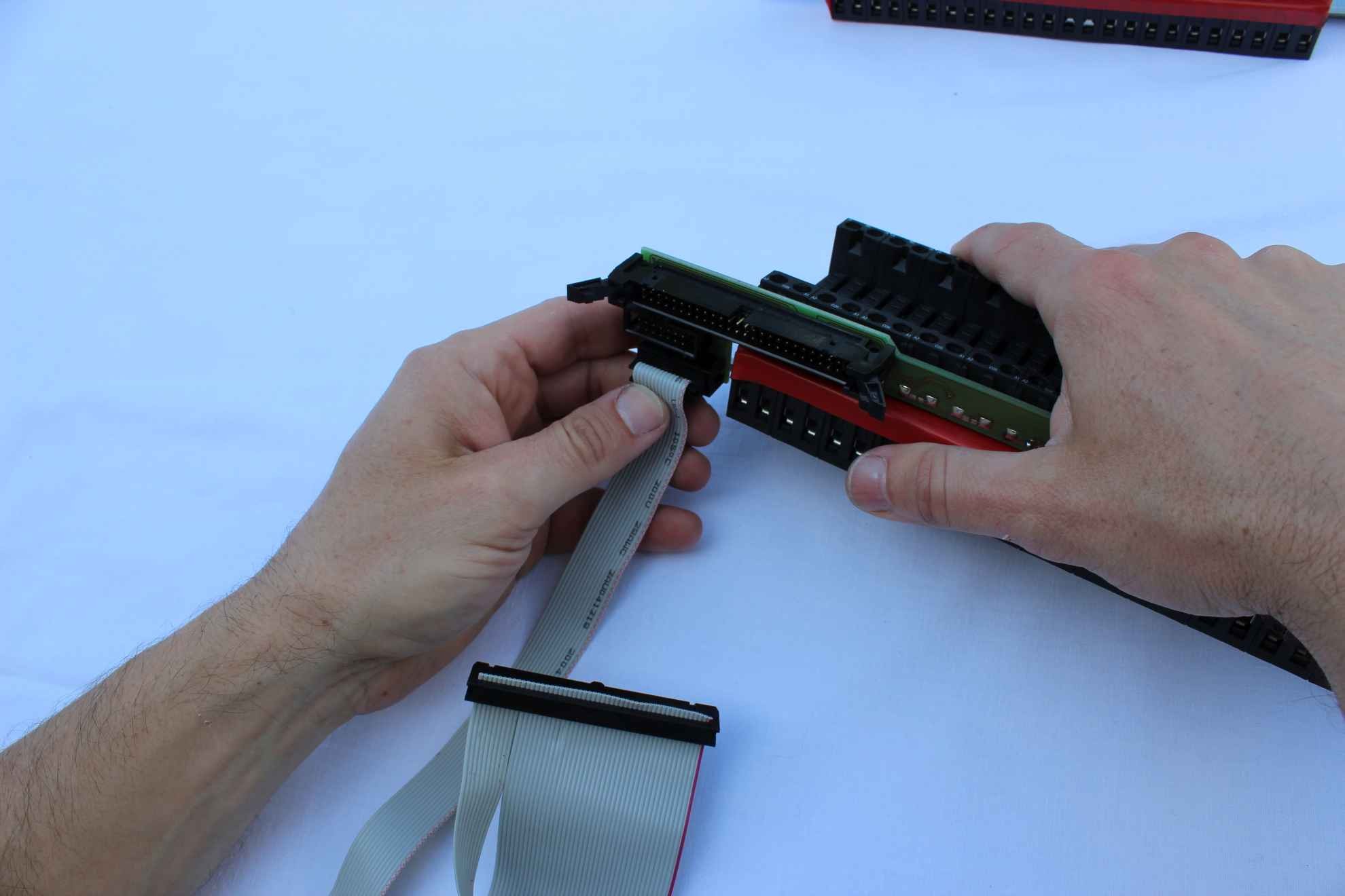
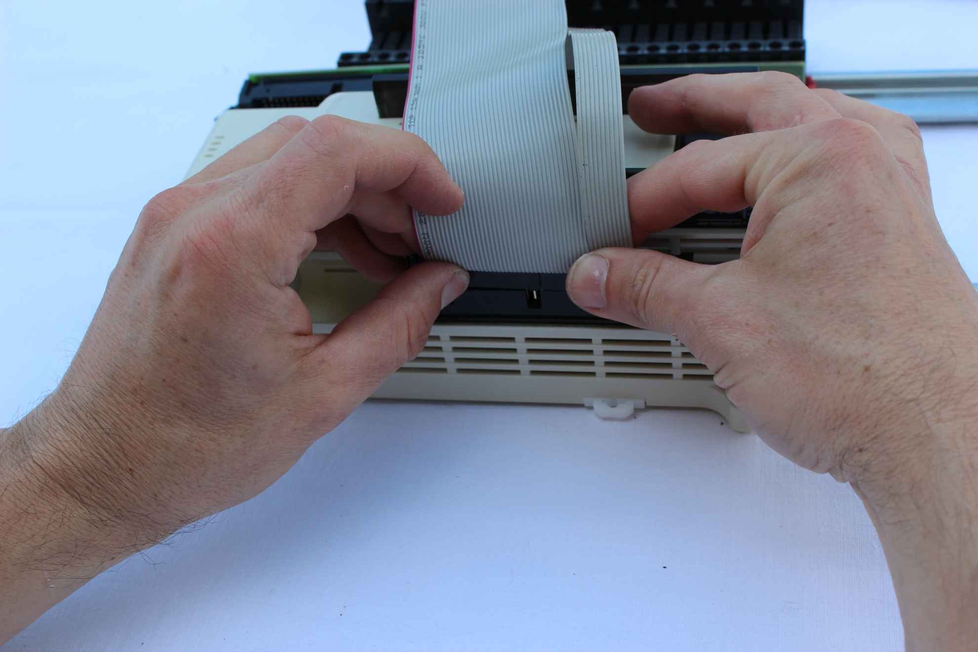
Installation of the basic relay module ( with large connector IDC-40 or 50 ) to the DIN rail .
Unscrew all the screws marked on the relay “COIL” (coil , both A1 and A2) to obtain a wider opening appears for the insertion tip side of the relay module .
Insert centered in the holes marked coasters “COIL”.
The protruding pins of the module should be in line with all the measures of these screws.

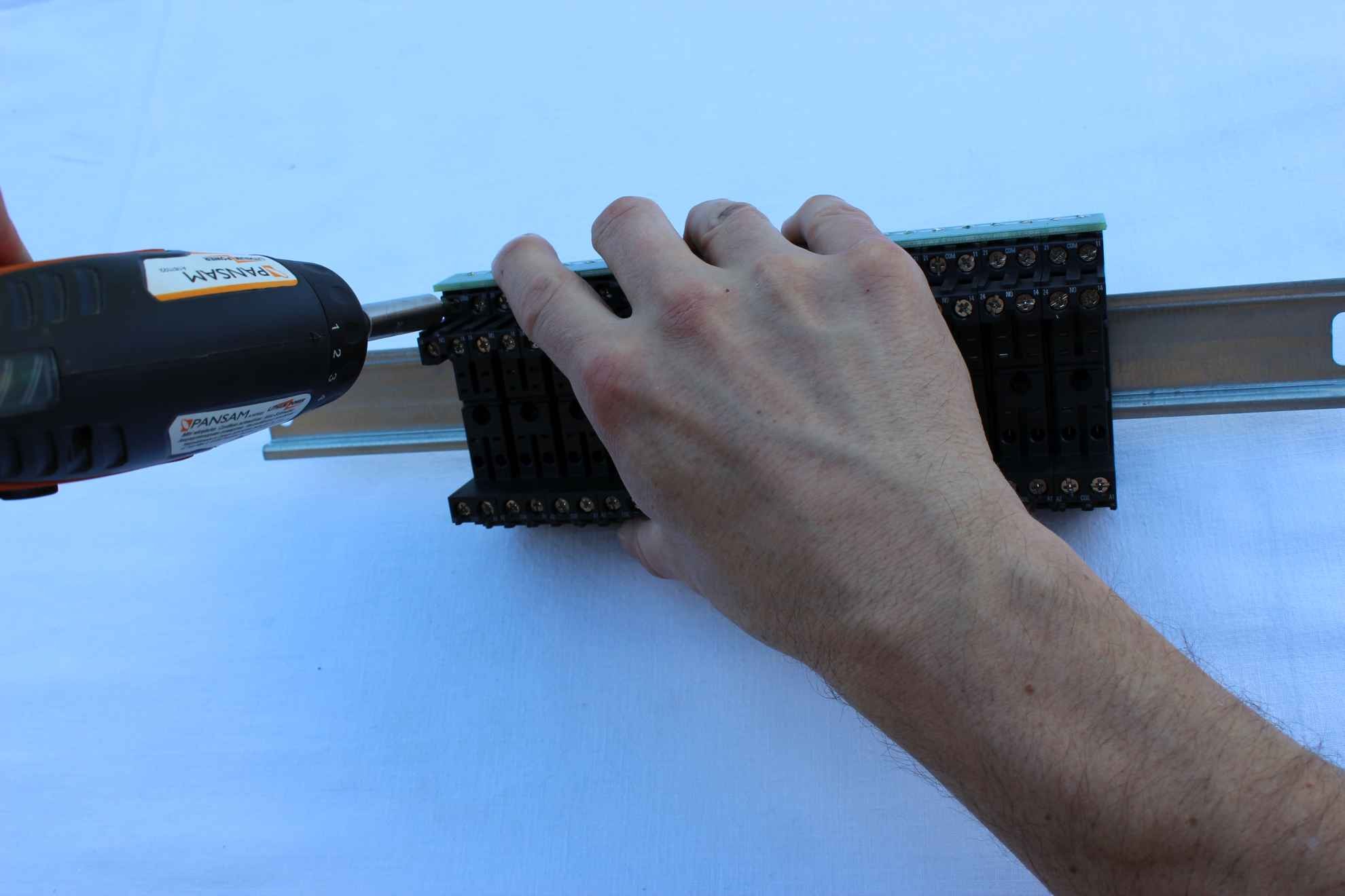
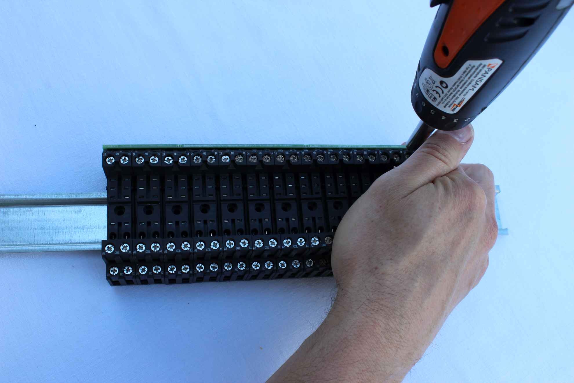
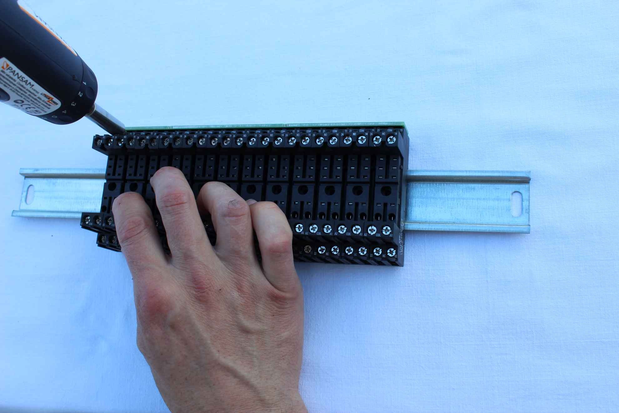
Screwing the screws first base for the relay module.
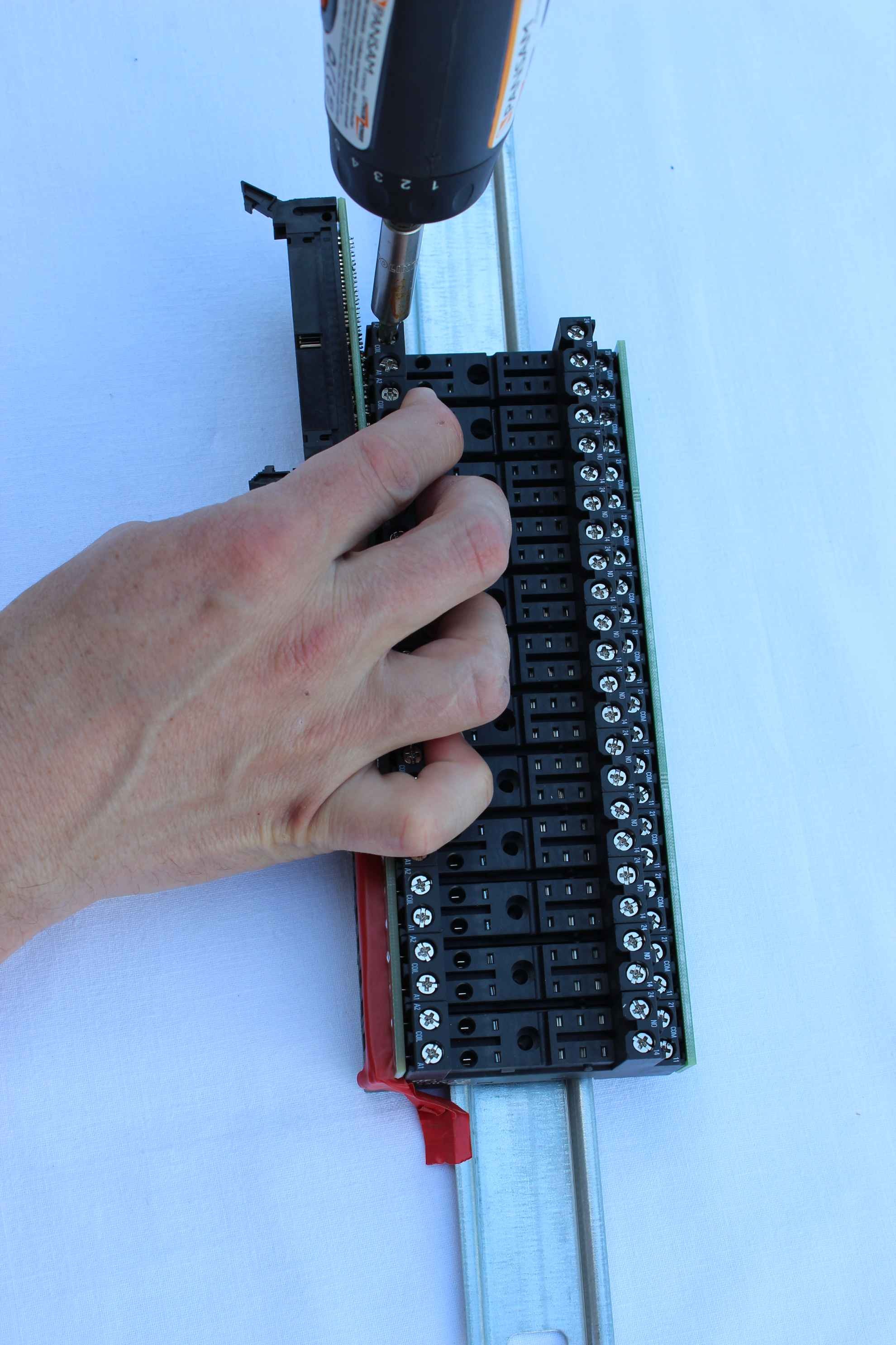
Screwing the screws last stand relay module while compressed relays.
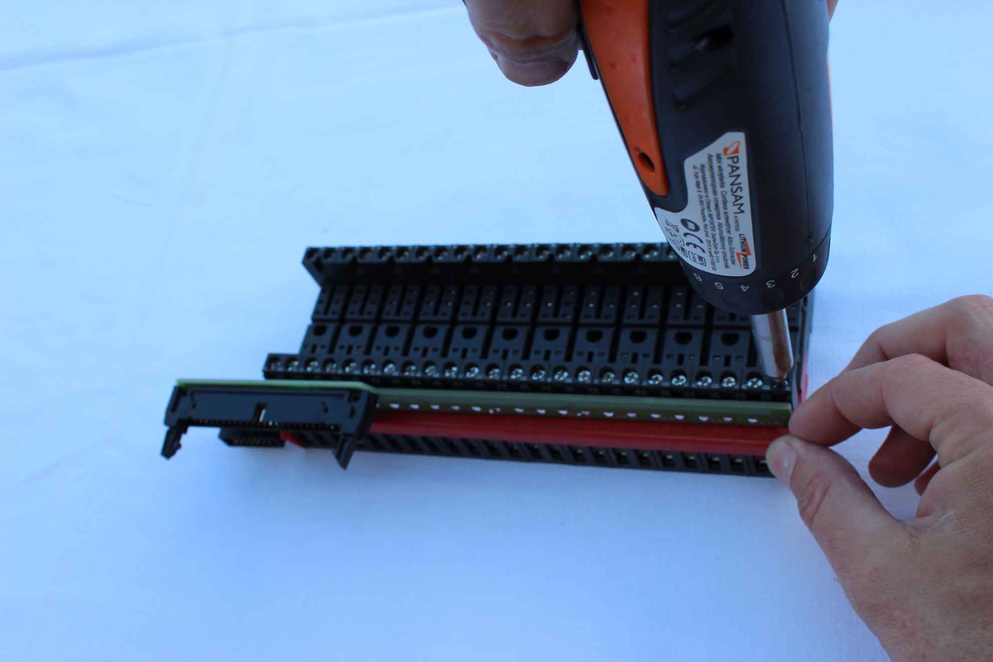
Screwing all the screws coil contacts ( ” COIL ” )
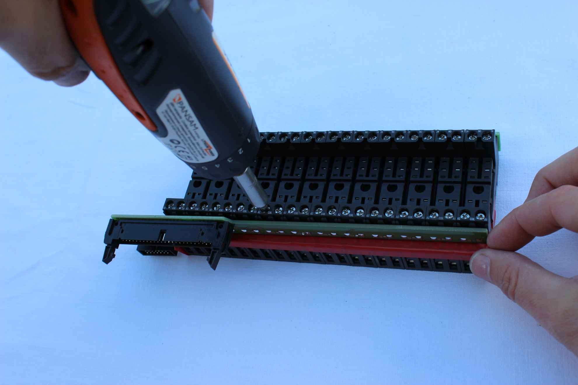
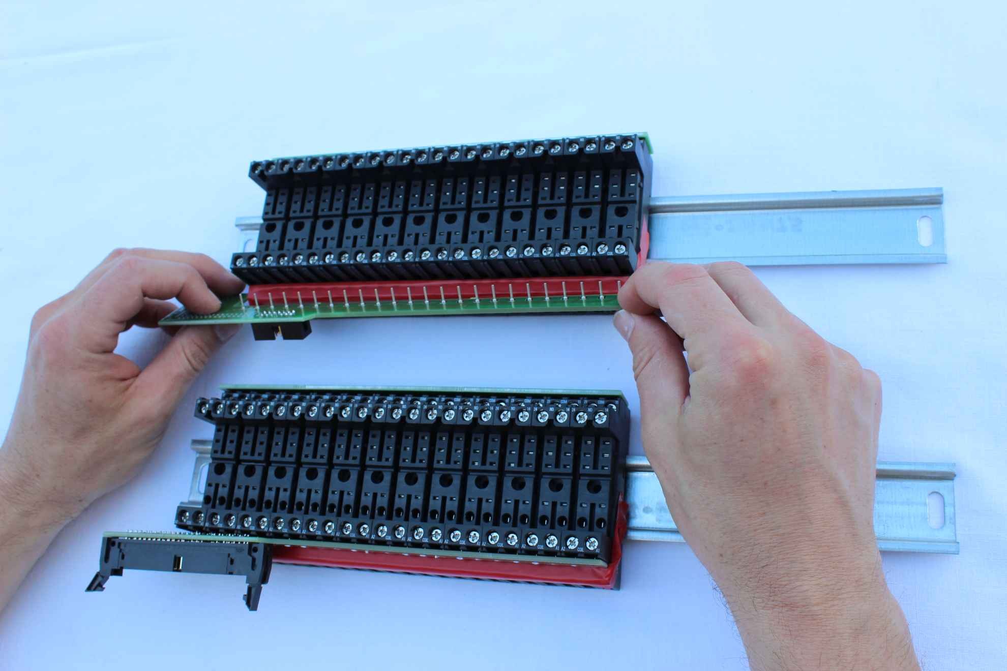
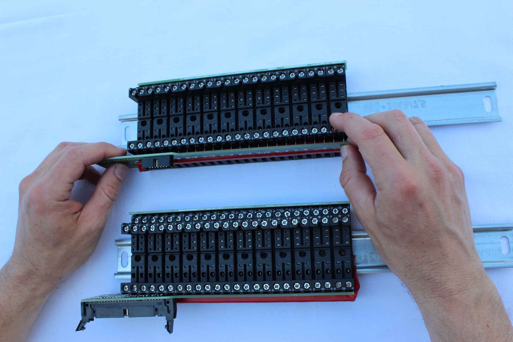
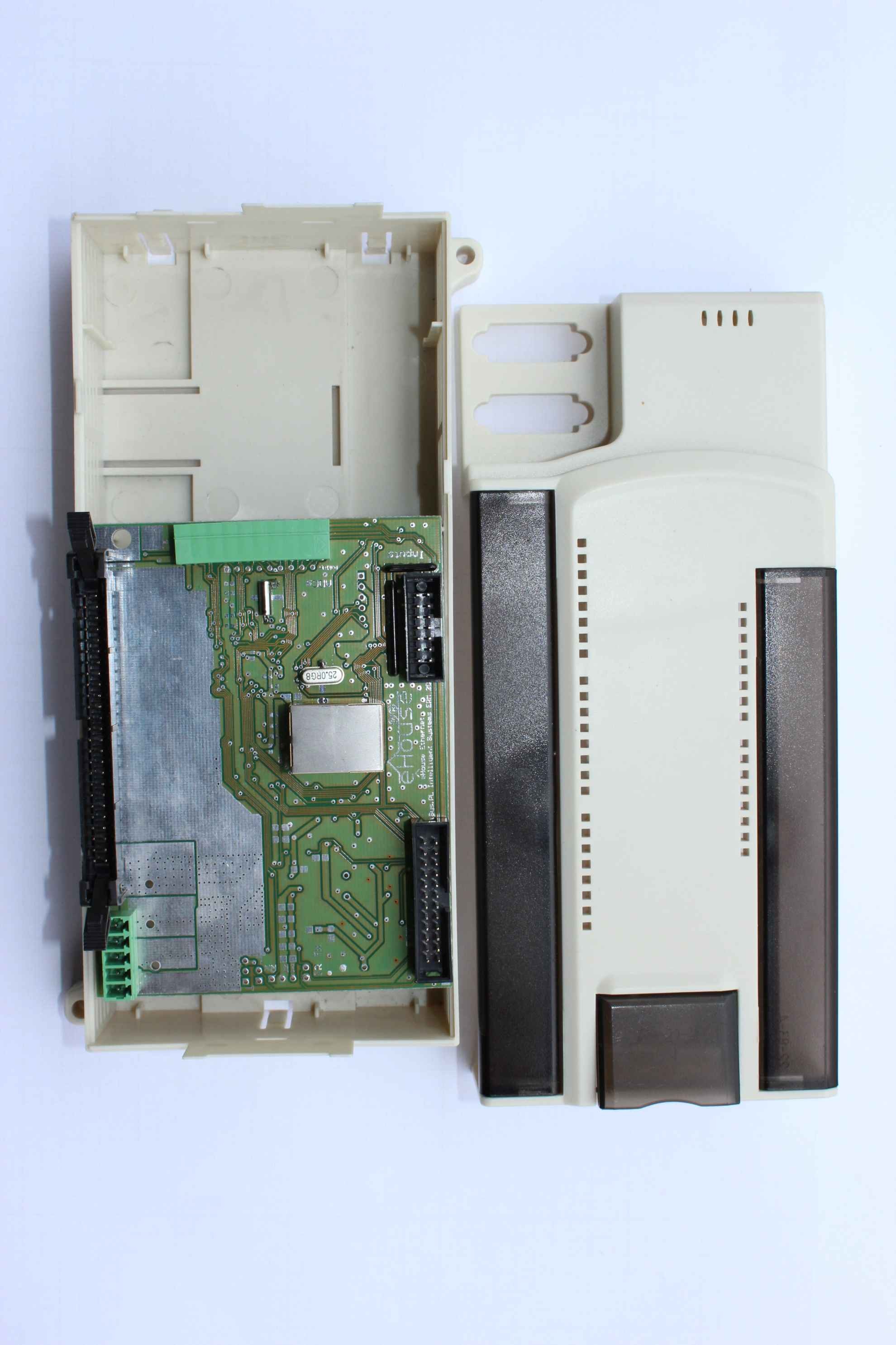
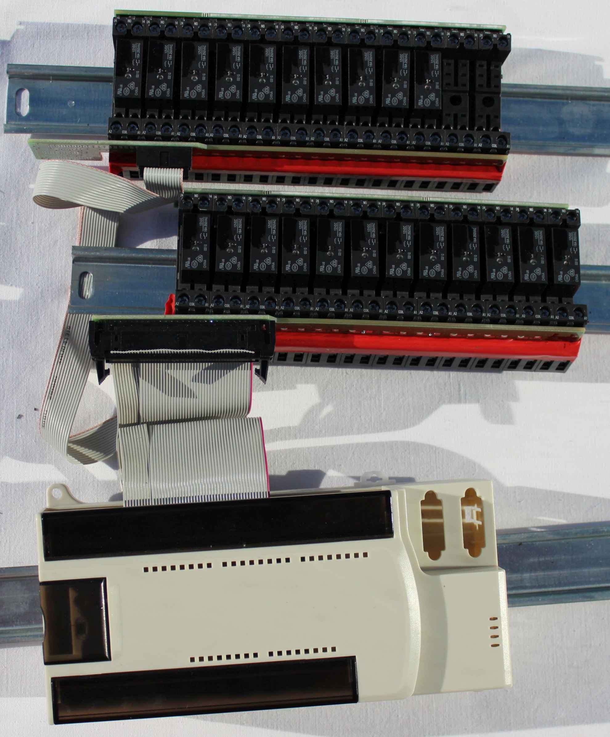
Photos assembled the basic module relays on each side :
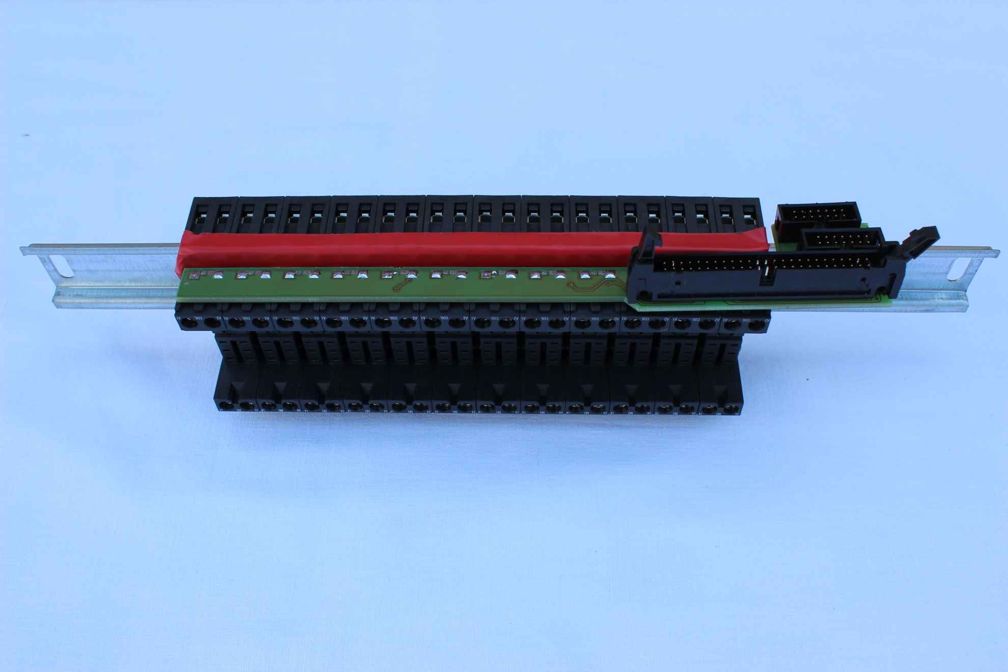
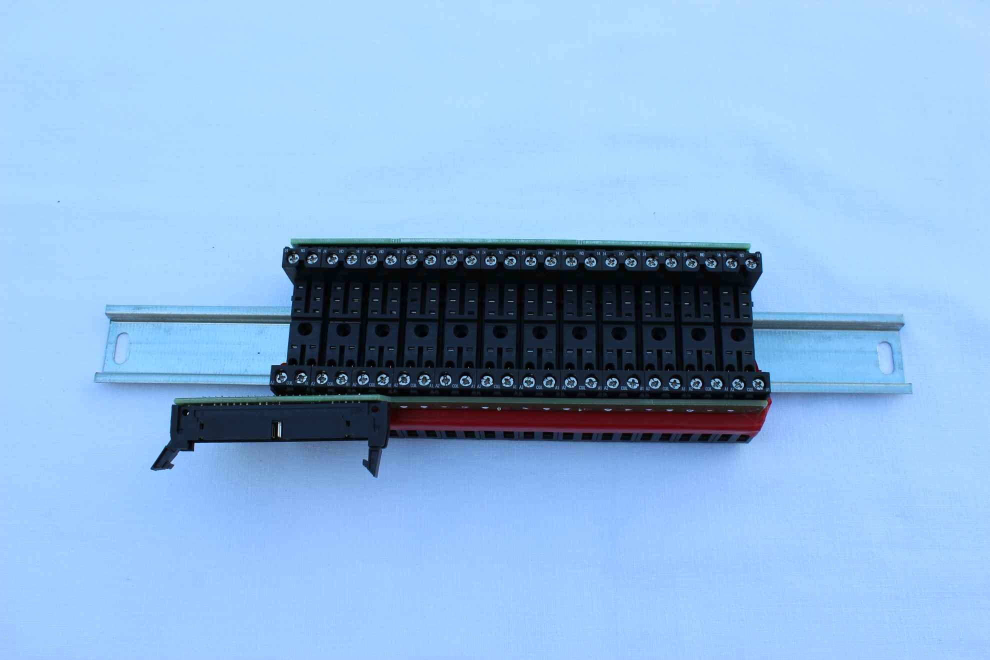
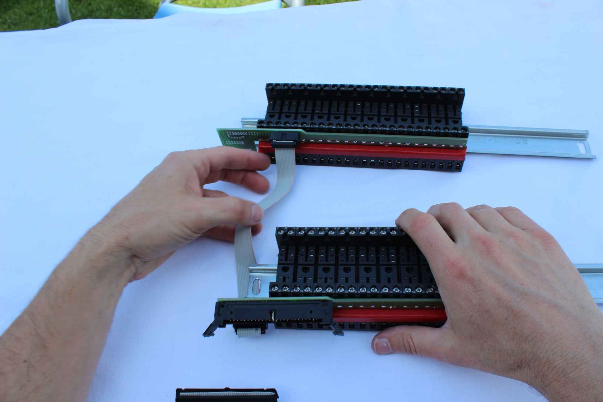
Identical to the basic module perform installation of expansion modules for additional DIN rail if necessary .
The only difference is that we take modules from a single IDC-14 connector instead of IDC – 50/40 , although there is no contraindications to use the same function of the basic module , and instead use a 14 -pin connector on the side of the second module connector pin 50/40 .
By pressing relays and screwing all the screws as before , we combine the basic module of enlargement flat belt connector IDC-14.
For expansion modules is one connector IDC-14.

For the basic module
- lower slot on the basic module – relays 13..24
- upper slot on the basic module – relays 25..32
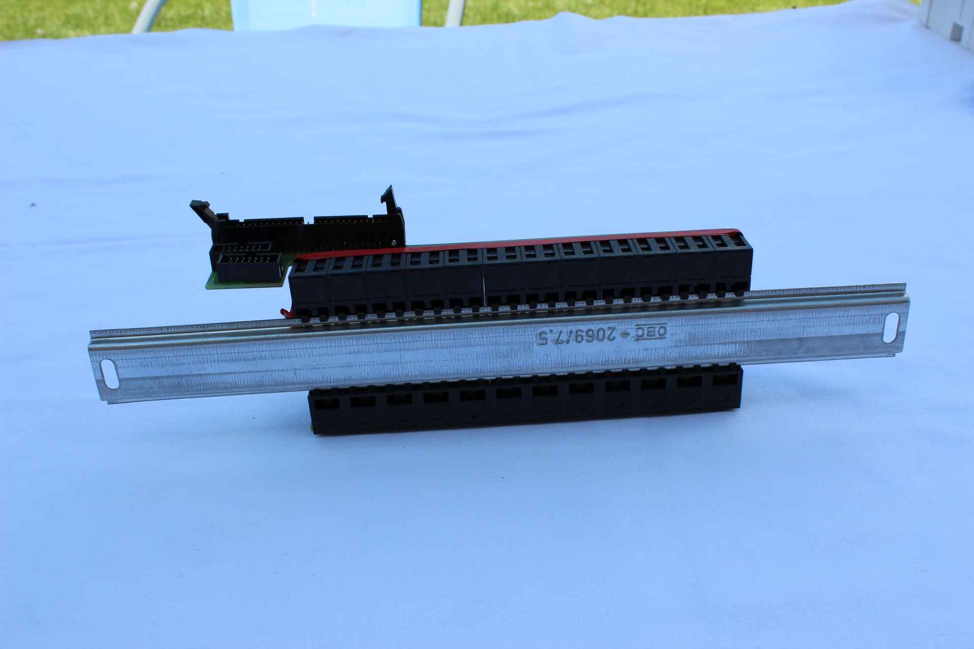
ERM can be installed in a separate housing outside the mini- – switchboard with DIN rails or outer casing (5 modular – micro switchboard ) .
ERM assembly on DIN rail in a mini – switching .


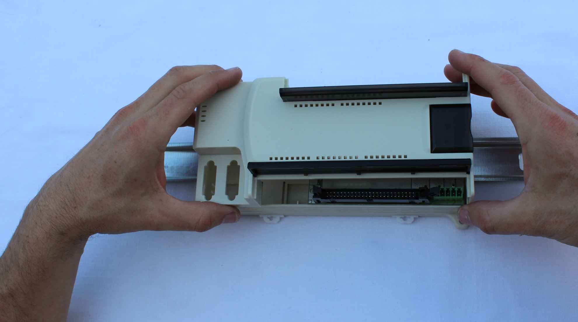
It is all part of the low-voltage switchboard (connecting the controller to the relay) .
Prior to the final location in the box are:
- Insert flat wires to the heat-shrinkable sleeves with wide margins in diameter without heating
- protect the varnish insulating layer about 1 mm all metal low voltage installation points
- remove the controller for laying cables with DIN housing
- tighten the wire – 3 wire to power controllers to a common power supply
- install a 12V power supply for LED dimmer (all power supplies in the system have to work on one phase and ground ( 0V ) must be shorted together grounded