eHouse.PRO Smart House professional distributor with the possibility of self-assembly.
eHouse.PRO Intelligent building for central switch-board: description of DIY for control whole building or floor.
Building Automation eHouse.PRO used for centralized installation, where all the wires go down to one place.
Building automation eHouse.Pro has the following features:
- 128/256 intelligent inputs come with alarm functions
- 128/256 intelligent outputs of electrical devices for switching on/off or drives (+/-/stop)
- alarm outputs with relay (siren, warning light, monitoring, silent alarm, early warning)
- Linux mini server 32b
- Communication interfaces and integration with other eHouse versions : LAN, RS-485, CAN, RF
Before continuing with we recommend you read the articles on connecting the eHouse.PRO system:
Intelligent Building eHouse.PRO connection of inputs
Intelligent Building eHouse.PRO connection of outputs
This professional switchboard (box) designed specifically for the building automation system eHouse.PRO enabling support for up to 128 intelligent outputs and 128 intelligent inputs.
Support for more I/O is possible by adding another distribution (electric box with relays and rj12 modules).
Features switchgear intelligent eHouse.PRO:
- Full metal enclosure closed with 2 locks Yale
- The door right or left individually mounted
- Dimensions of switchgear 1000 * 850 * 150 (box) – Flush
- Outer frame dimensions of 1060 * 900 * 160 – the plaster (5 mm). Detachable front.
- Switchboard Weight: empty (25kg), assembled (~45kg)
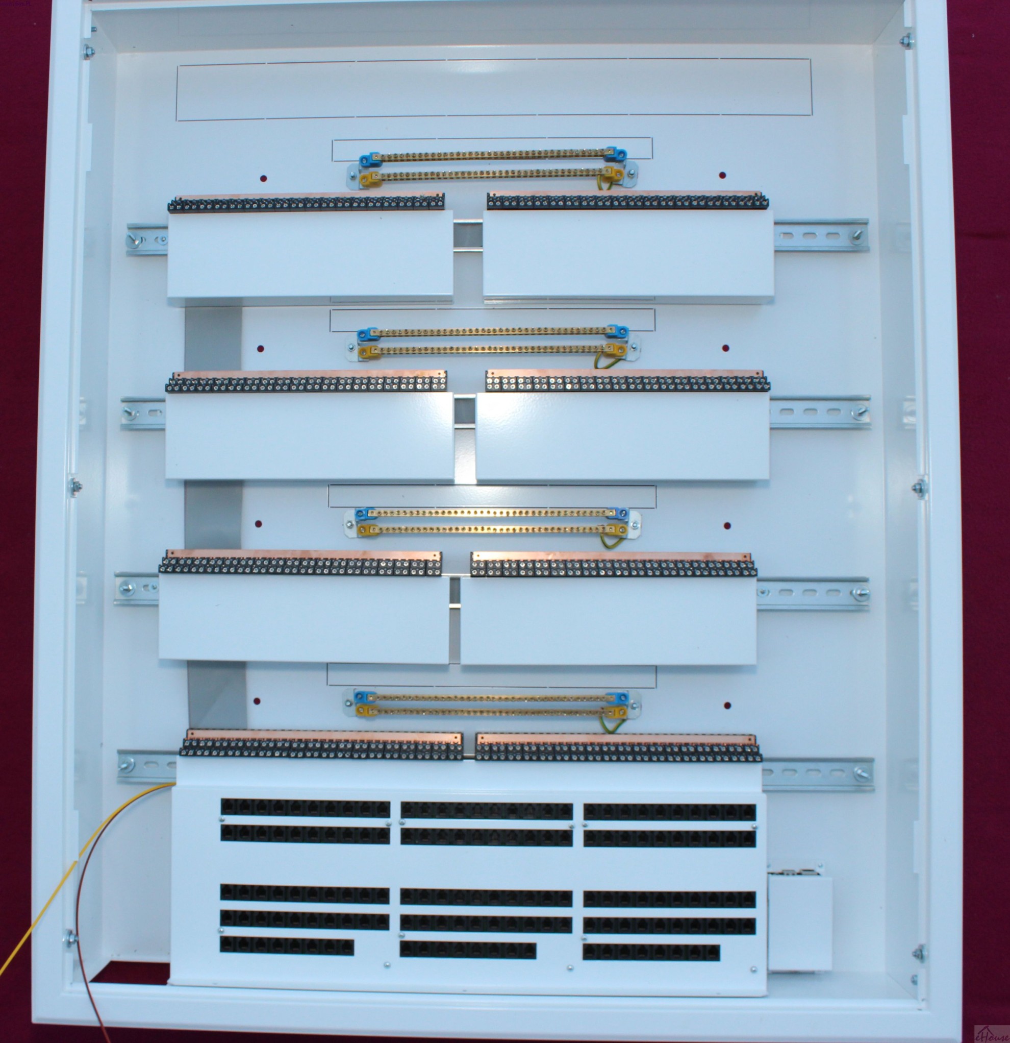
- 4 DIN rail (TH) for mounting 2 relay modules MP-18 each, an additional supply of about 10 modules on the rail
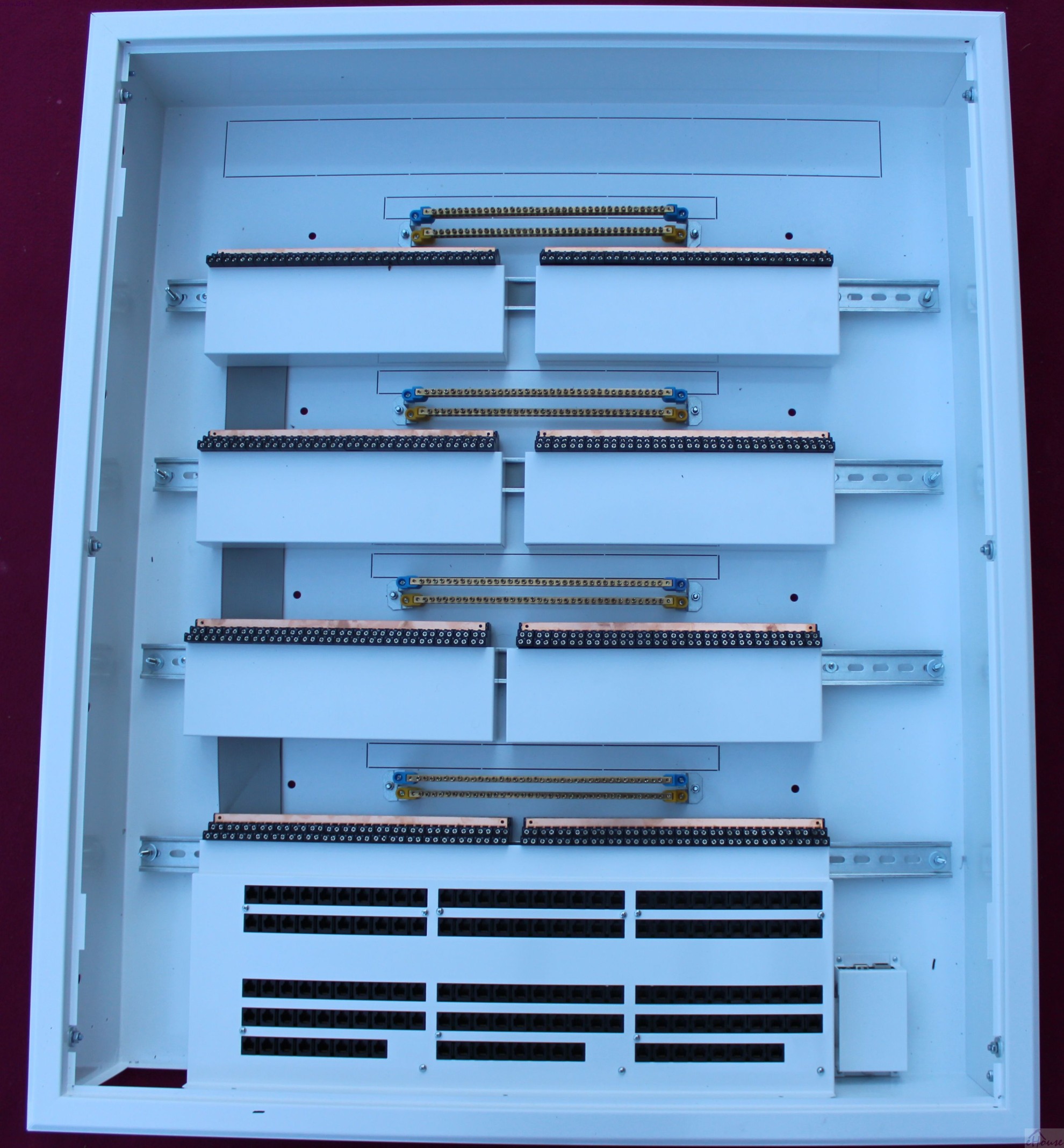
- 4 * 2 rails make contacts for protective conductors and neutral (32 points)
- RJ-12 connectors to connect switches, sensors alarm
- Ability to install up to 2 power suplies LED/RGB 12V/8A (eHouse LED PS)
- 8 holes for mounting box to the wall (on the sides)
- 8 holes for mounting box to the wall (the back of the box)
- Ability to entry 230V cable into box for 5 ways to reduce the number of 230V wires in a box to a minimum. Holes for cables are masked available to cut off.
- Wiring Hole RJ-12 jack for connecting sensors, switches
- Metal shield/cover for electronics (low-voltage components to protect against puncture or accidental short circuit to high voltages)
- relay modules with relays 230V/16A and stands DIN rail to provide 4.5cm of insulation between low voltage and 230V
eHouse.pro Switchboard can be purchased as a totally assembled or can be assembled yourself “DIY” based on the following instructions.
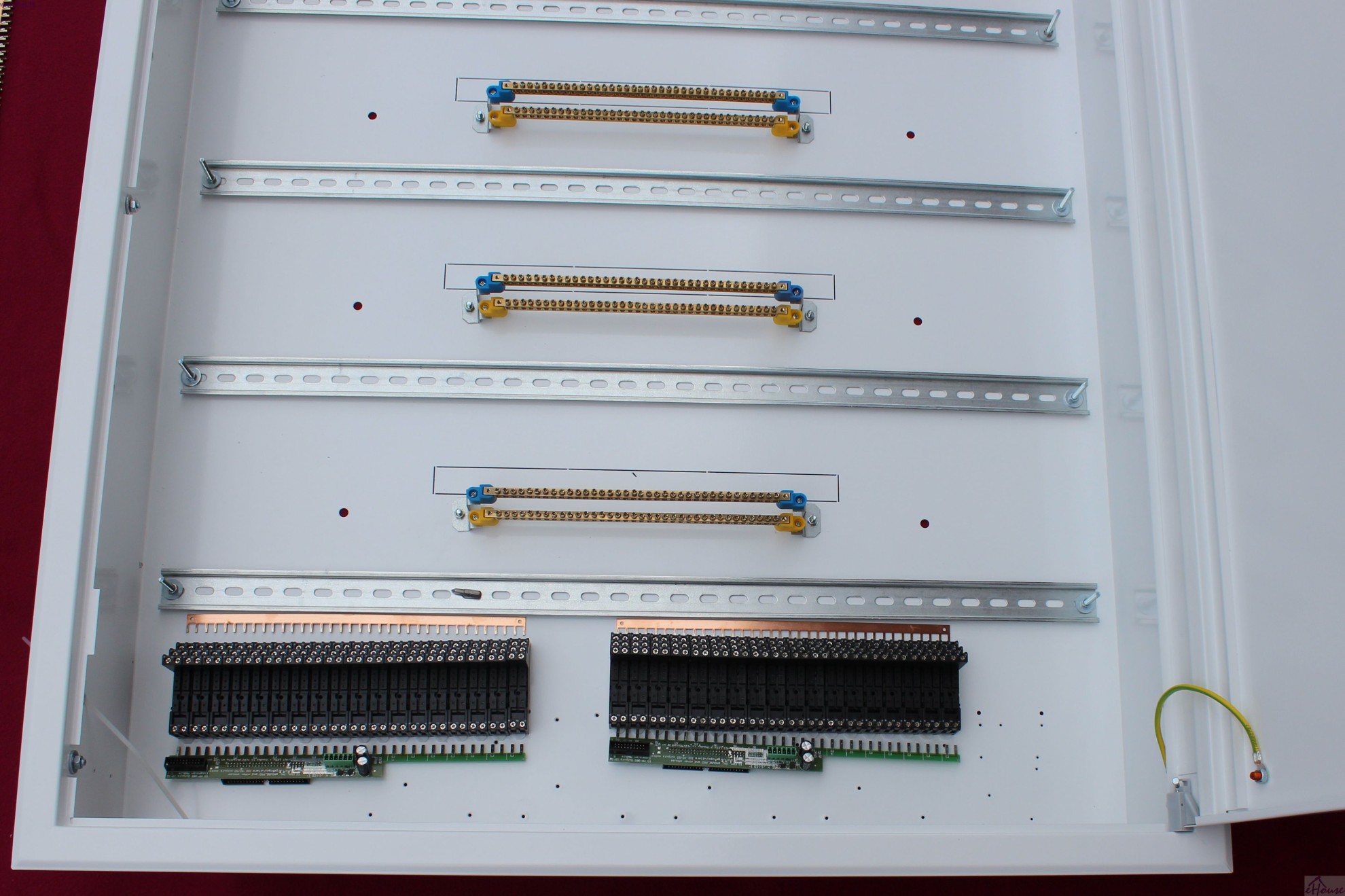
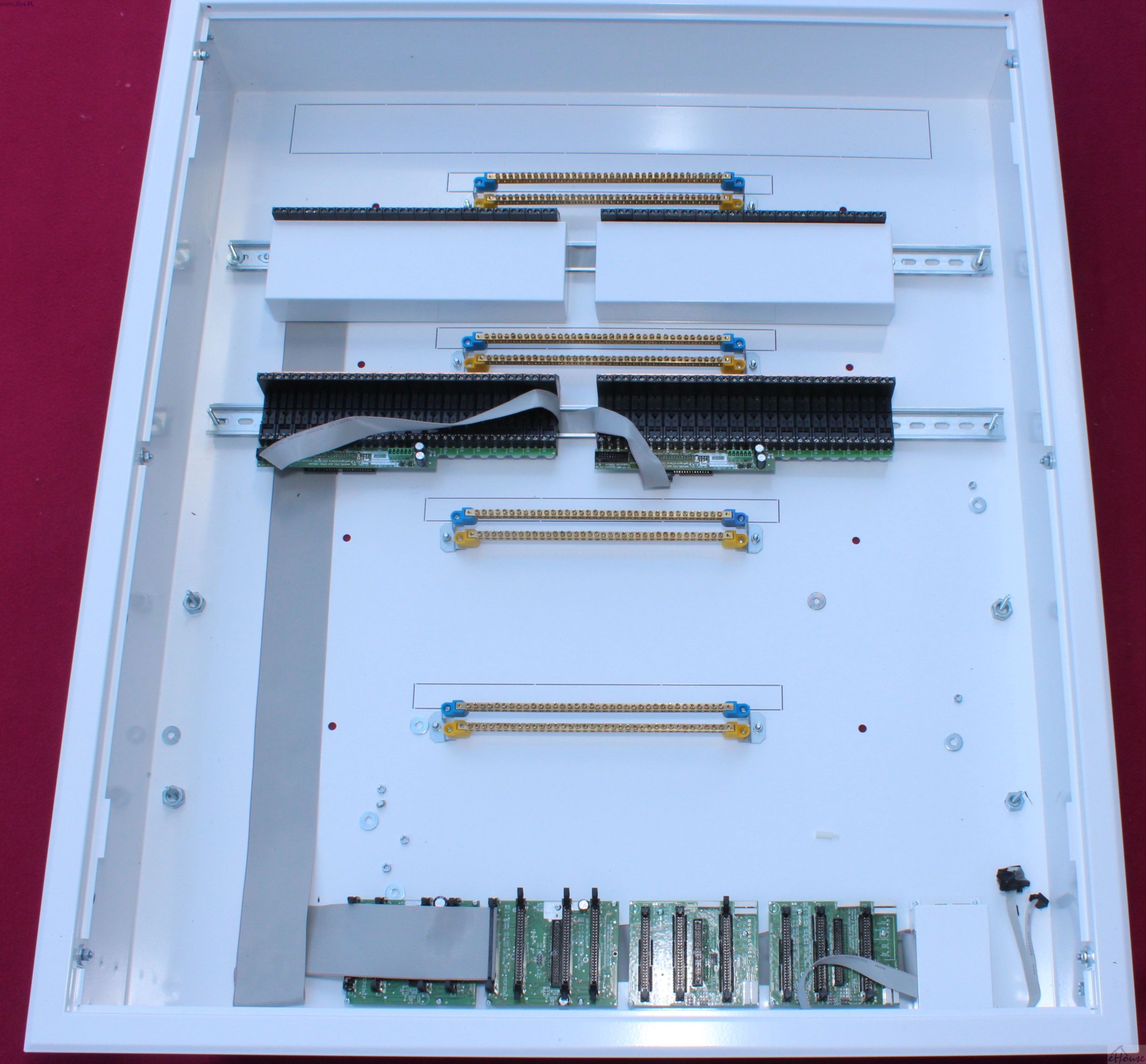
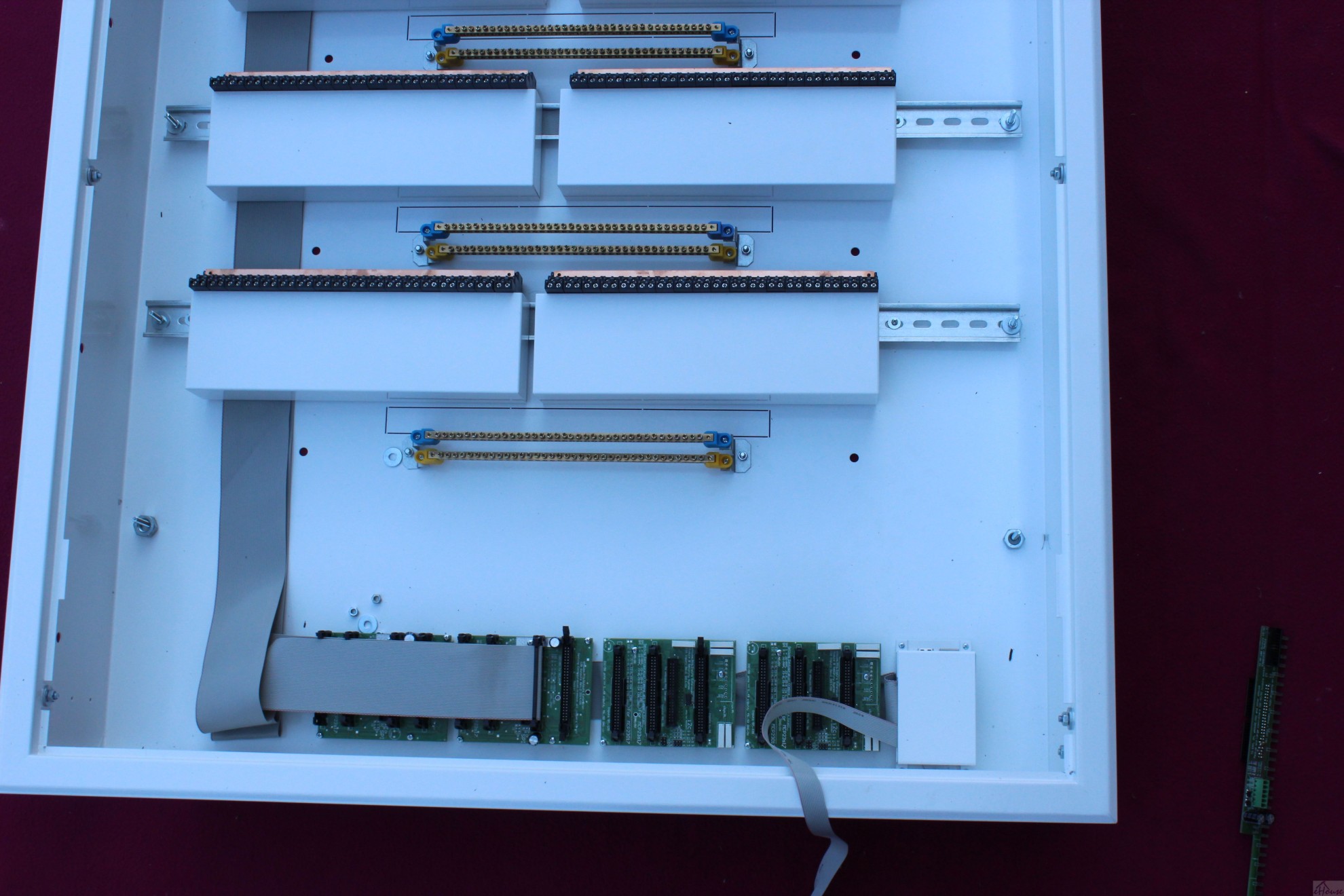
An empty box distribution center

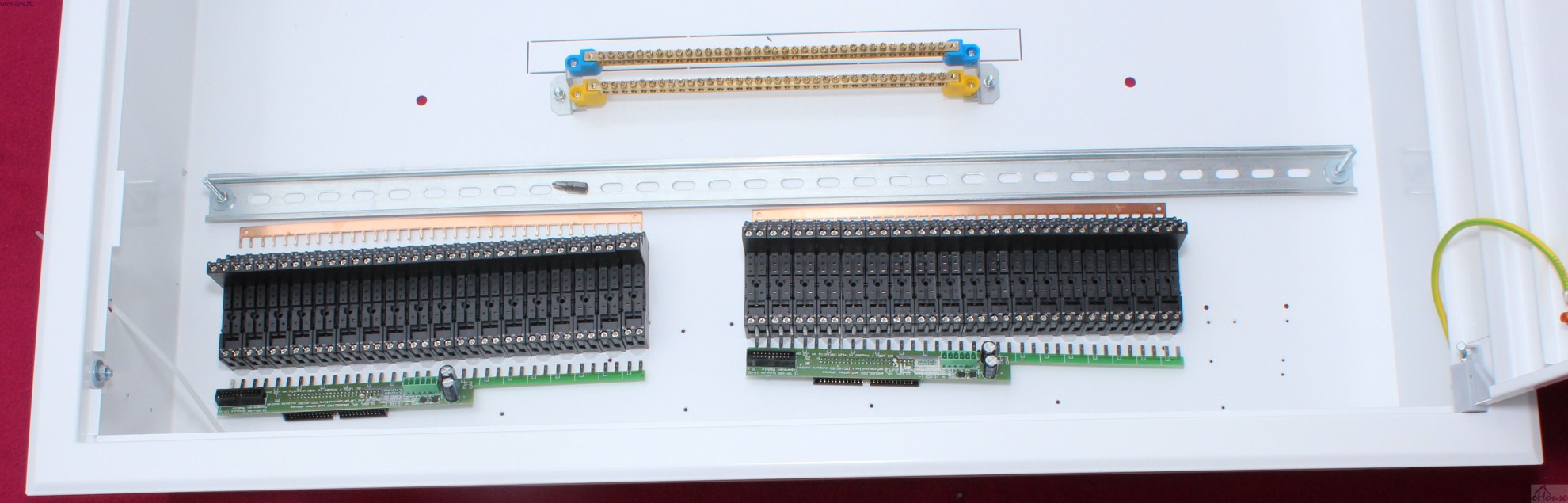
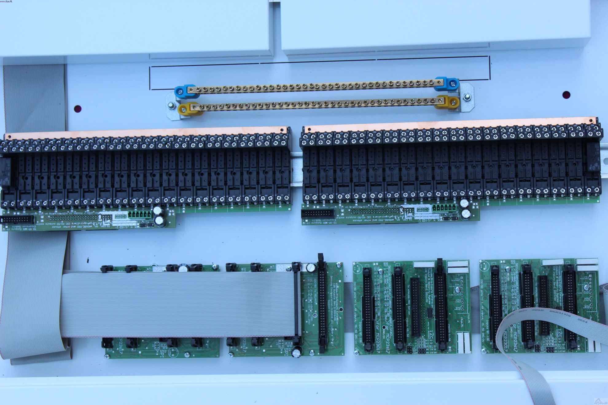
Relay modules prior to assembly. Comb copper is used as the common rail COM relay contact.
The PCB realizes the transition from tape IDC-50 directly to the coil of the relay on a DIN rail (TH).
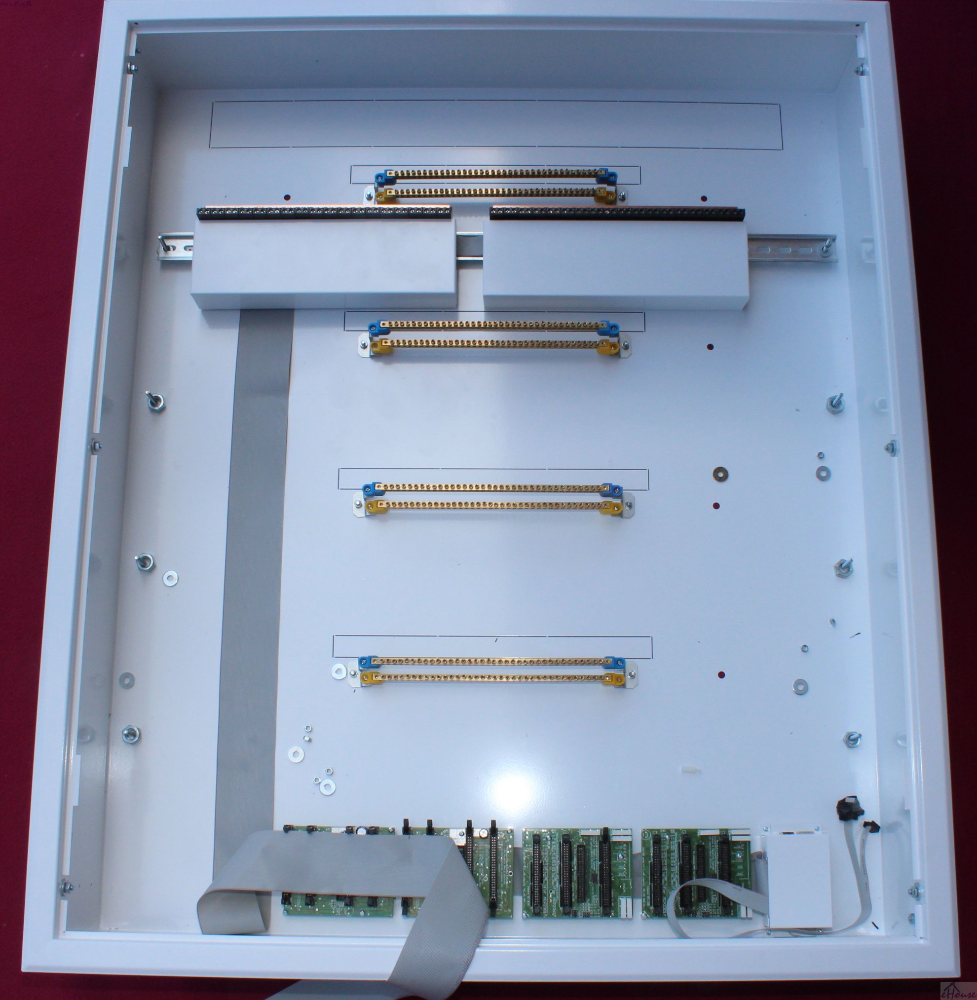
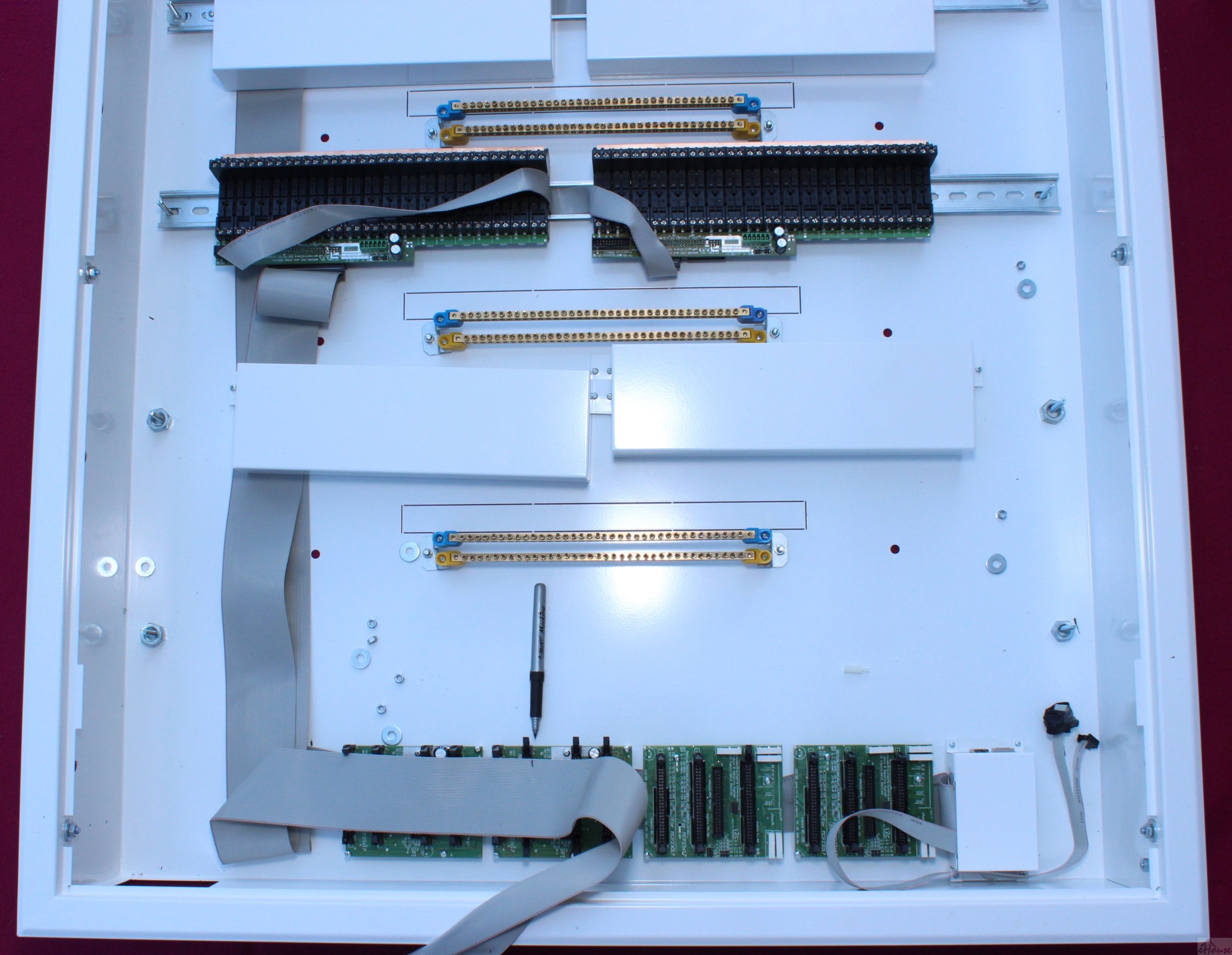
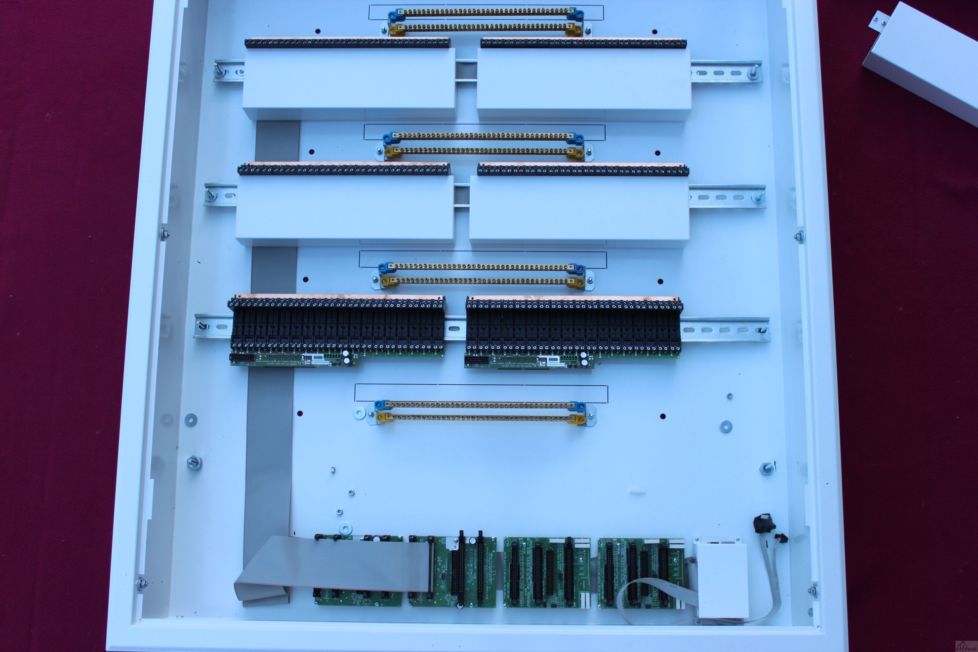
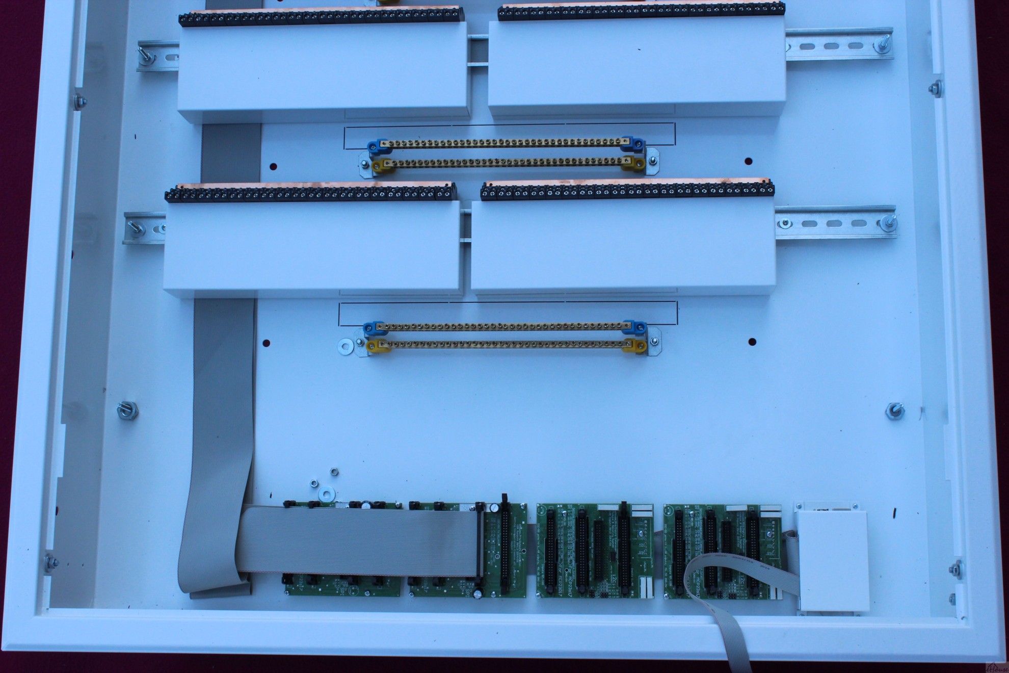
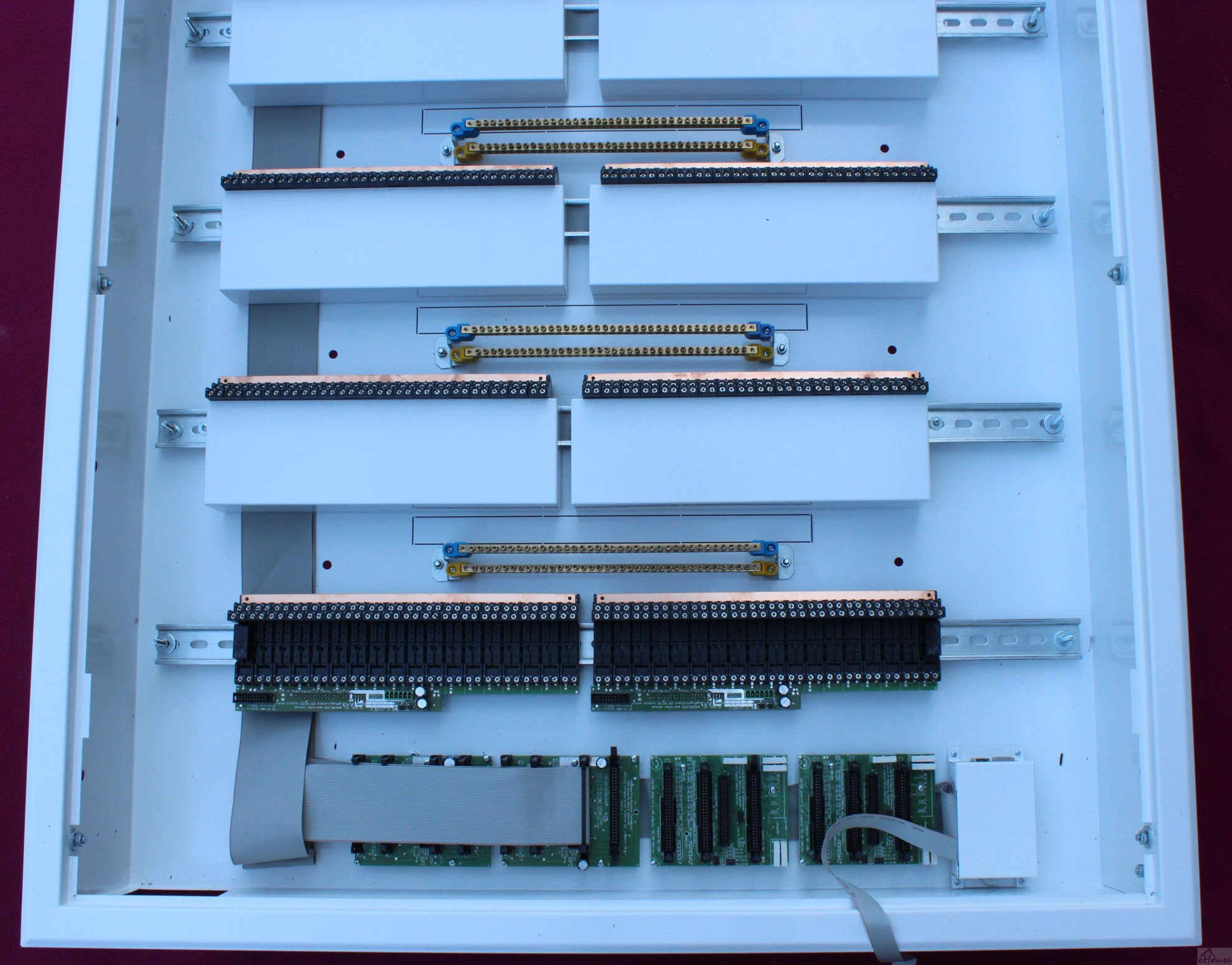
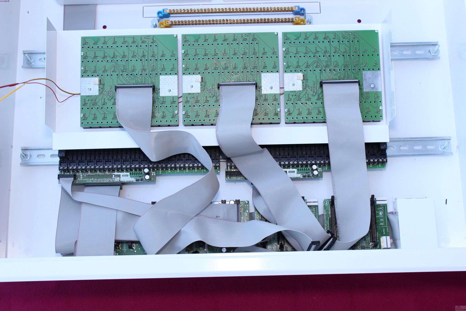
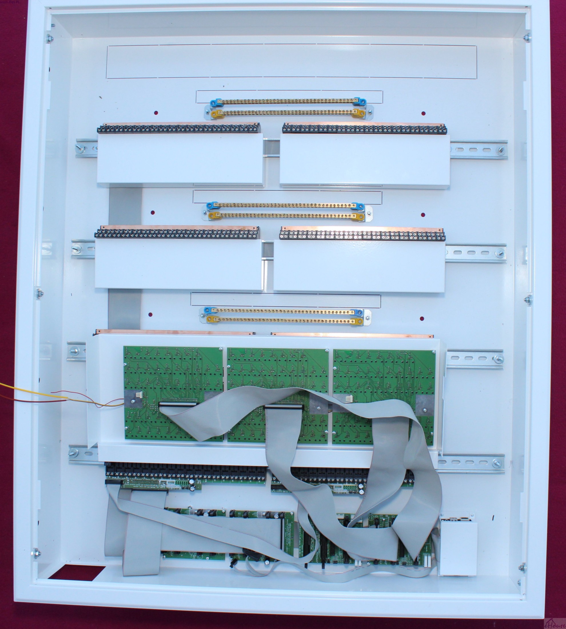
Electronic modules of intelligent inputs and outputs and a microcomputer is secured in a metal screen.
2 output modules (support up to 256 outputs) and 2 input modules (supporting up to 256 inputs).
Intelligent I/O Modules are screwed via 15mm plastic distances.
The electronics are installed at the bottom of the box for best cooling.
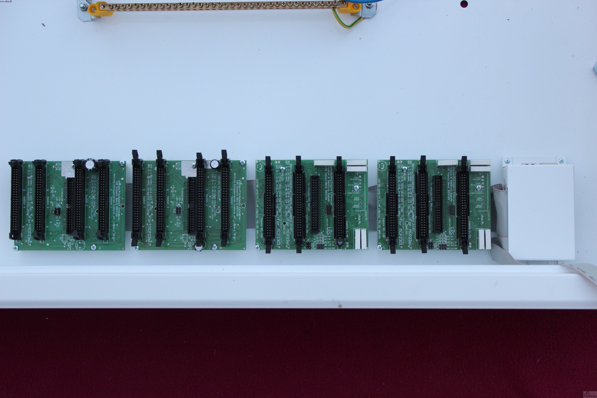
Starting from the left:
1) Intelligent Output Module 129-256 – set by jumpers
2) intelligent output module 1-128 – set by jumpers
3) intelligent input module 129-256 – set by jumpers
4) Intelligent Input Module 1-128 – set by jumpers
5) microcomputer ARM Linux
If you do not use all 256 inputs and outputs you do not need to install the appropriate I/O modules.
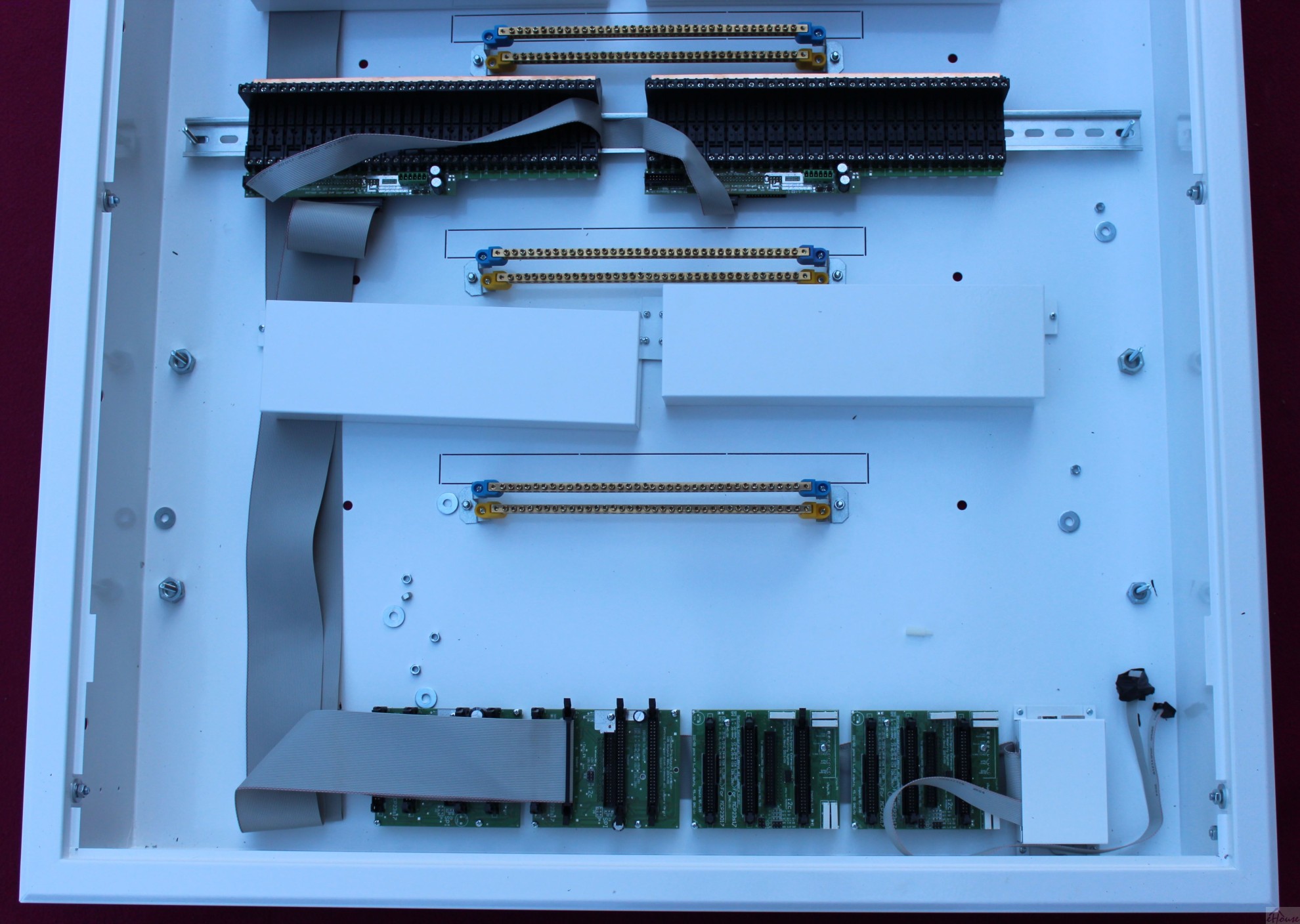
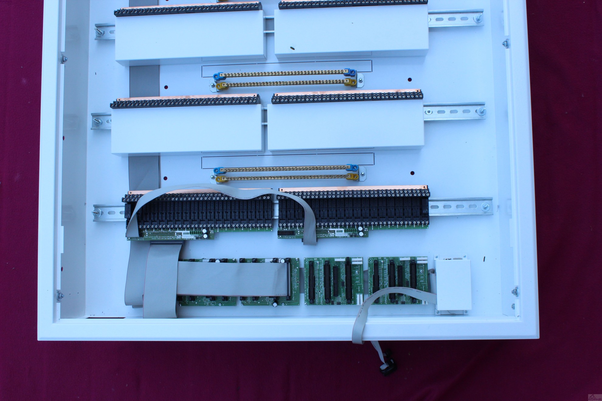
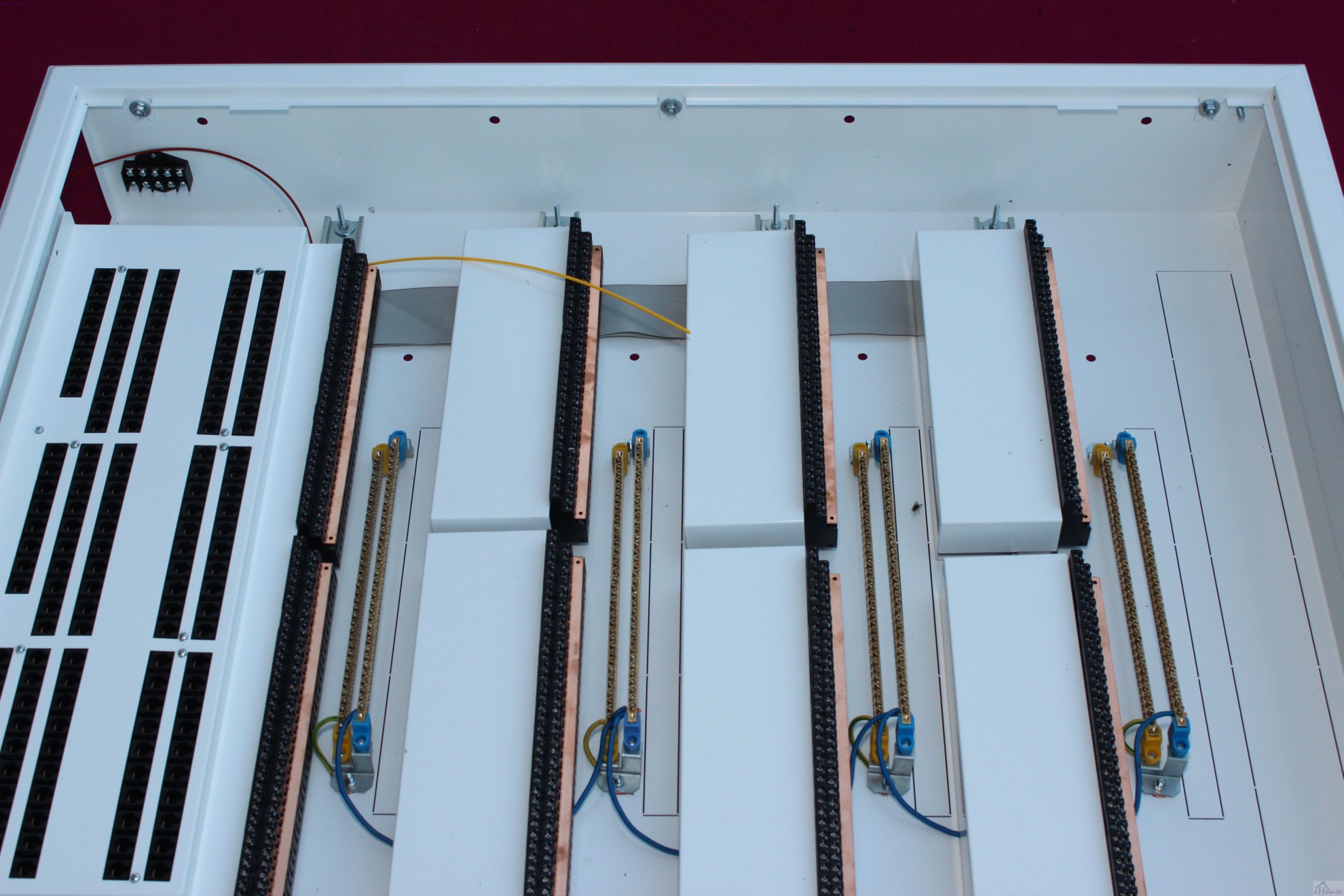
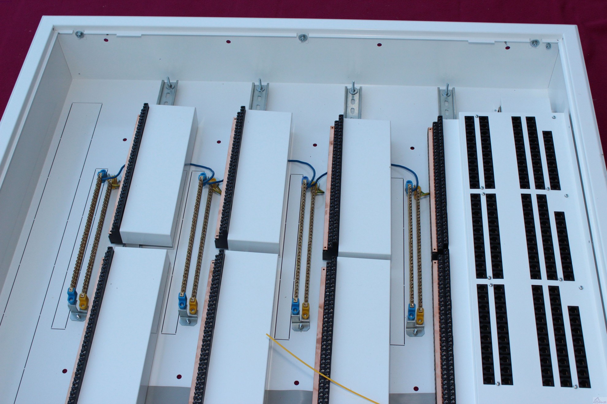
The easiest way to install relay modules is start from the highest DIN rail/TH.
IDC-20 flat tape (length about 70cm) is used to connect the relay modules and extending basic 1-18, 19-32.
DIN rail should be raised by placing caps of about 10mm to facilitate their installation.
We bend IDC-20 flat cable and put between modules within the DIN rail for protection.
In addition there are installed 4 additional relays 33-36 which is not connected to the electronics. Their coils can be connected to other relays example, to enable 3-phase voltage, 2 speakers, etc.

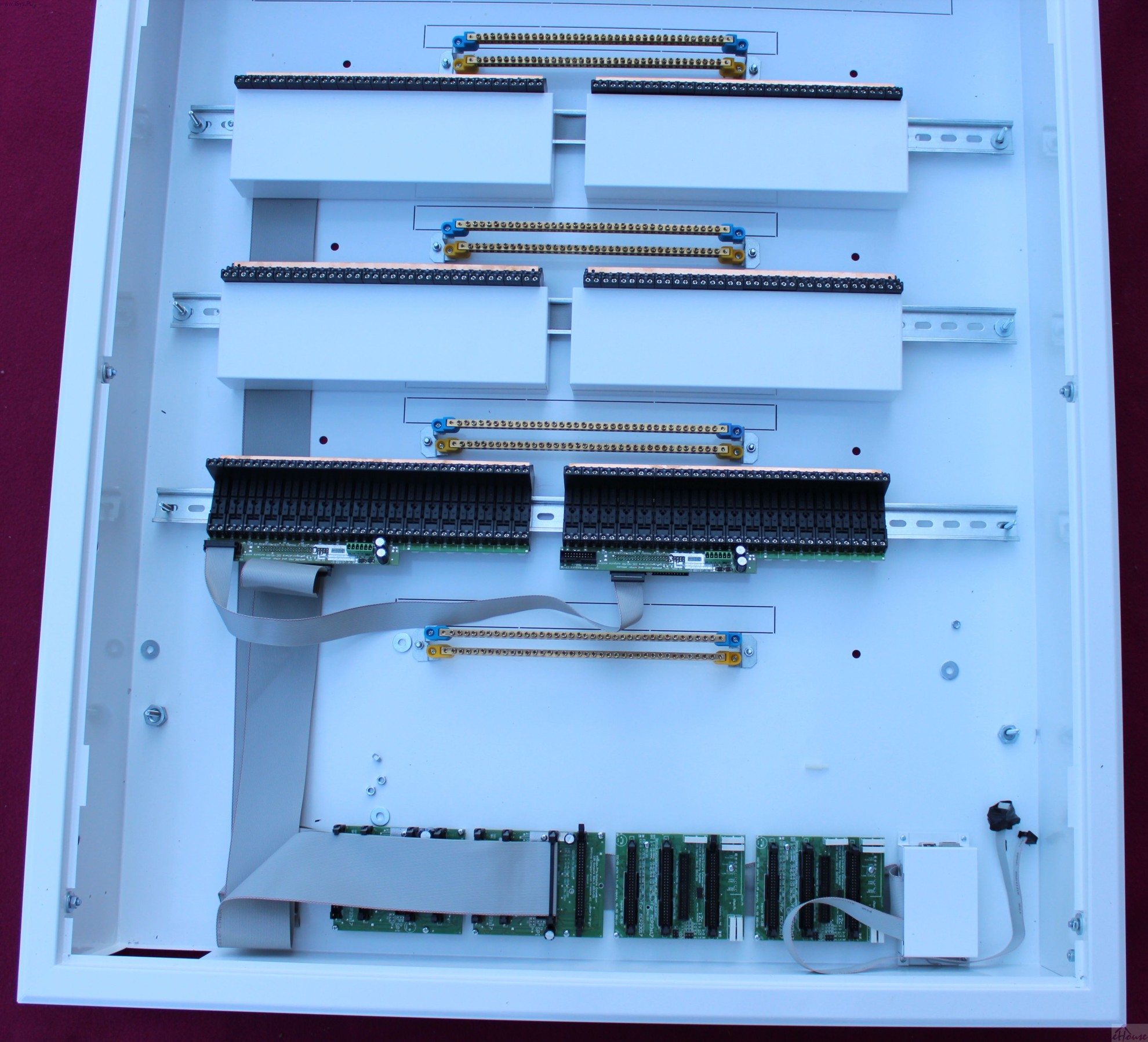
Tape flat IDC-50 with a clamping socket is put into the IDC-50 and eversion of approx. 6-8 cm upwards and downwards due to the design of the mask and leave the store for possible alignment / adjustment of cable length.
The length of tape IDC-50 respectively from the upper DIN rail / TH (130cm, 114cm, 96cm, 55cm)
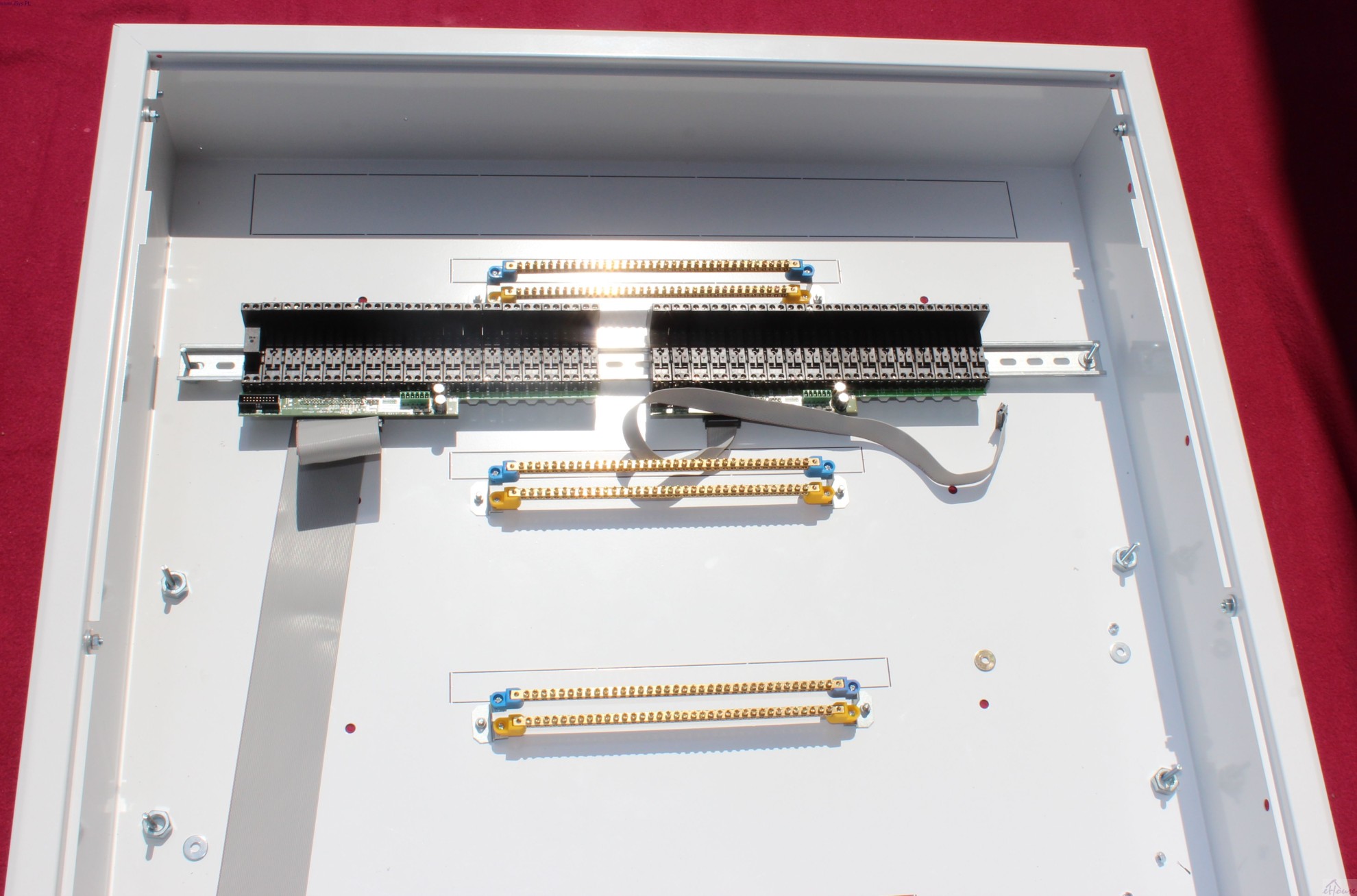
We put all or only used relays to sockets.
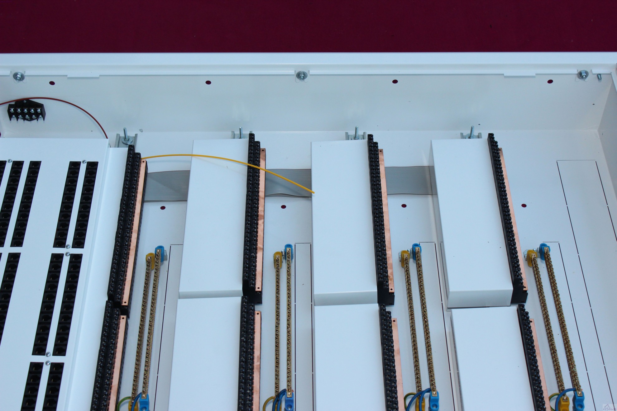
Then, we assume masking “on standby” to stabilize the wire IDC-50. Move the tape IDC-50 up to the left so as not to interfere with installation holes box.
Grills are screwed on one or both sides, depending on how much space you want to save.
After screwing shield/cover bend the tape at the end of the box 360 degrees and 45 degrees to plug in up to 2 output module (1-128).
To perpendicular to trim the tape to the desired length, use the set square to mark the intersection.
The tape is cut normal acute and long tailor’s scissors. IDC crimped crimper and assumes the pin.
Without taking out the cotter pin IDC-50 from the slot IDC-50 is almost not possible without damaging the cable.
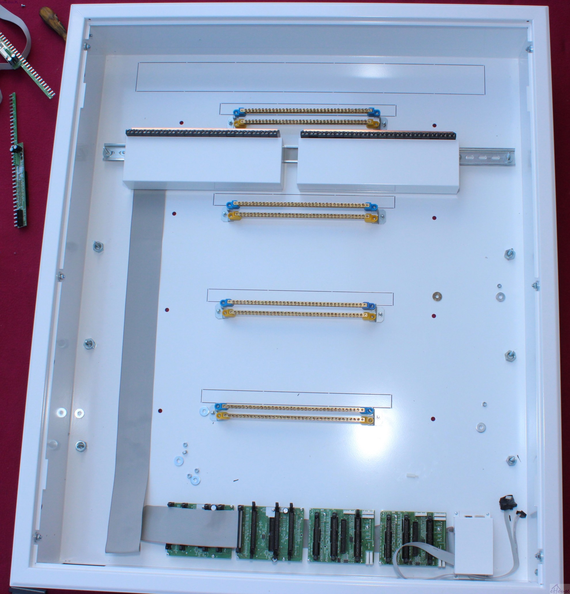
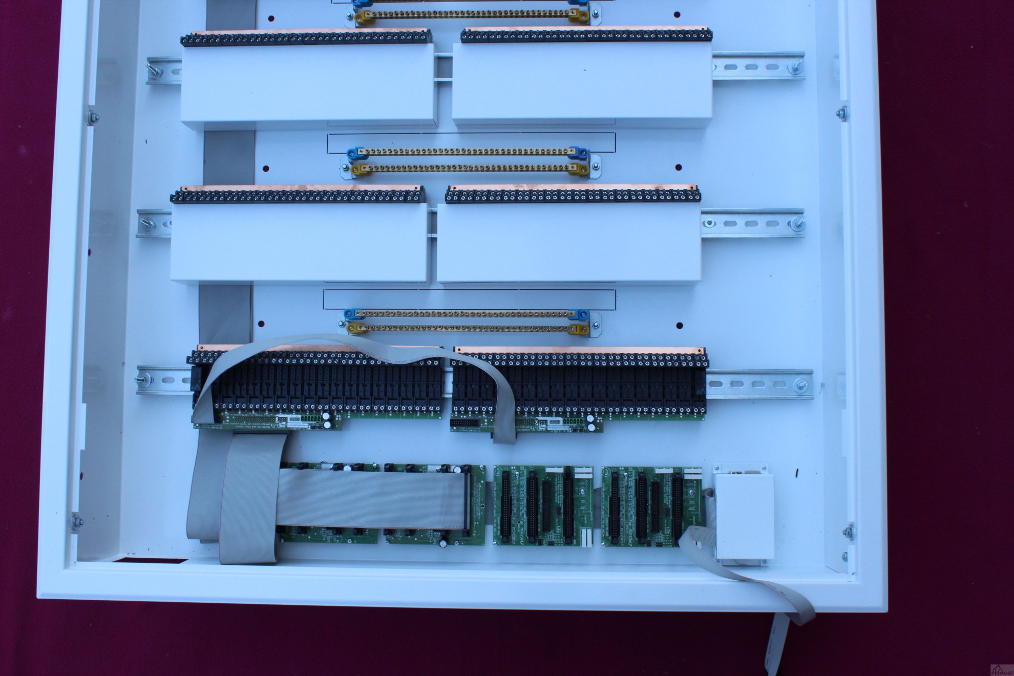
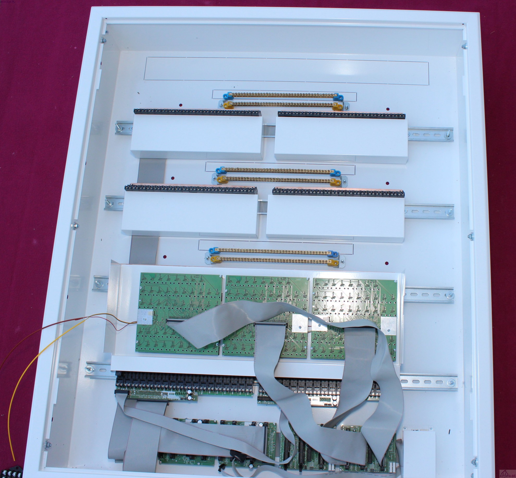
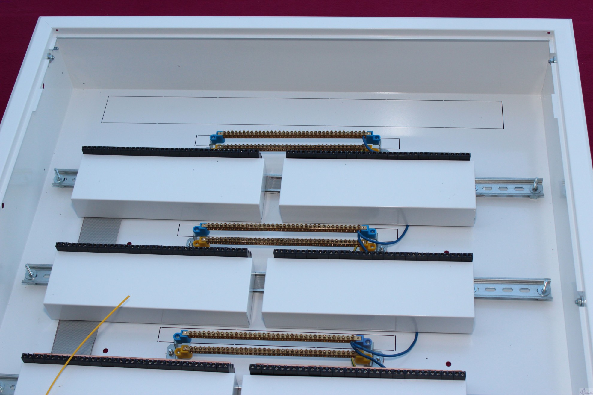
We go to the next pair of relay modules (2 DIN rail from the top) analogous to the first.


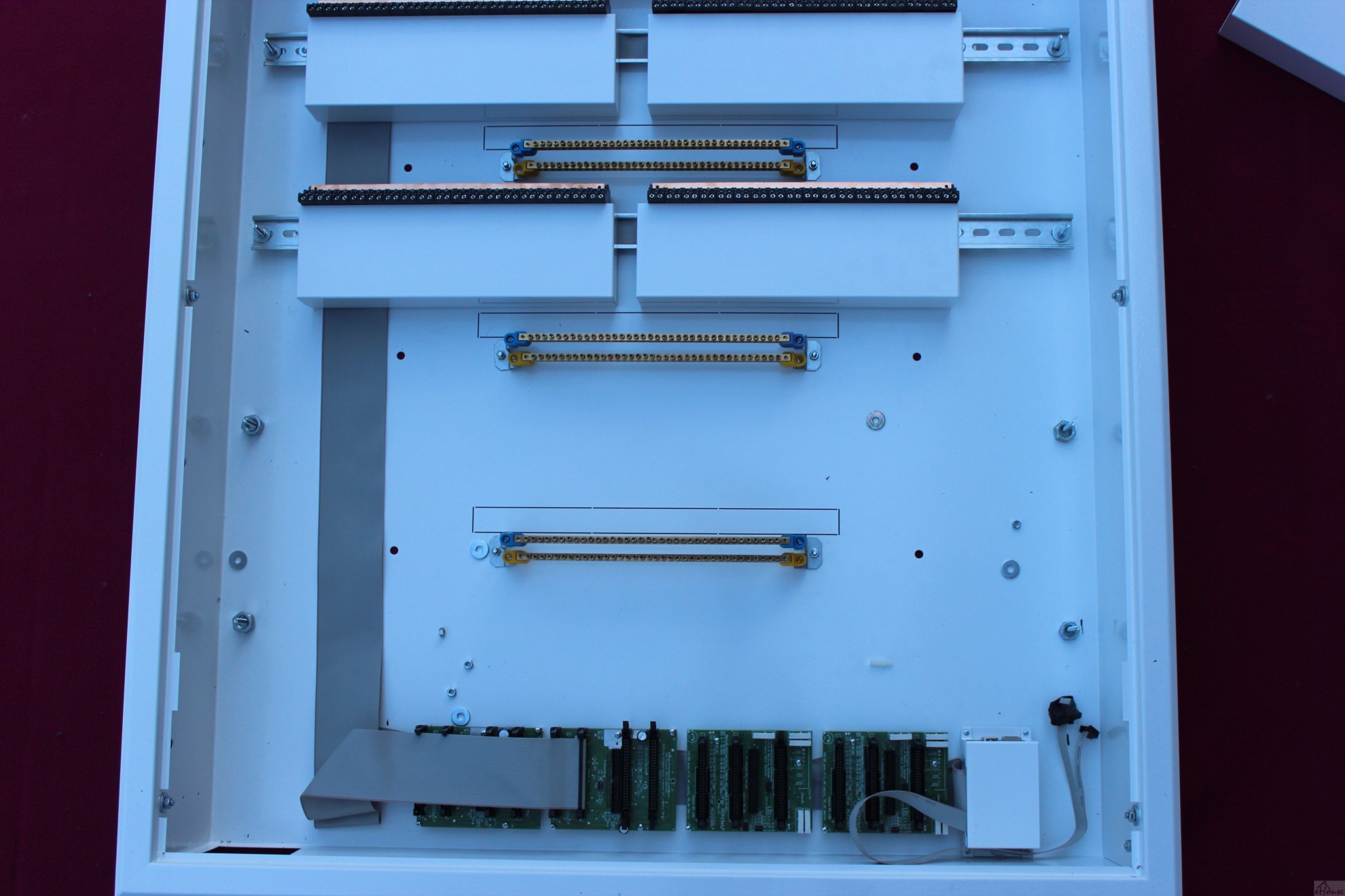
Go to the next pair of relay modules (3 DIN rail from above) in analogy to the first and second.
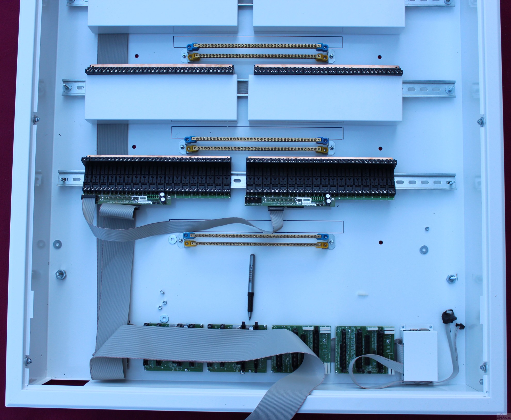

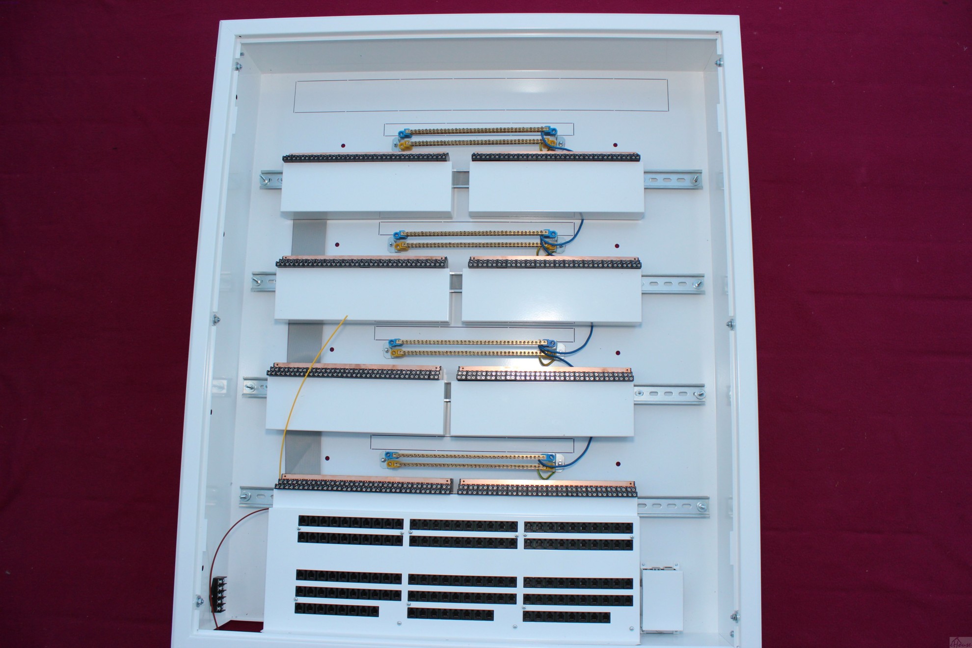
Then we install the 4 pair of relay modules (lower DIN rail) analogous to the previous but without bezel.
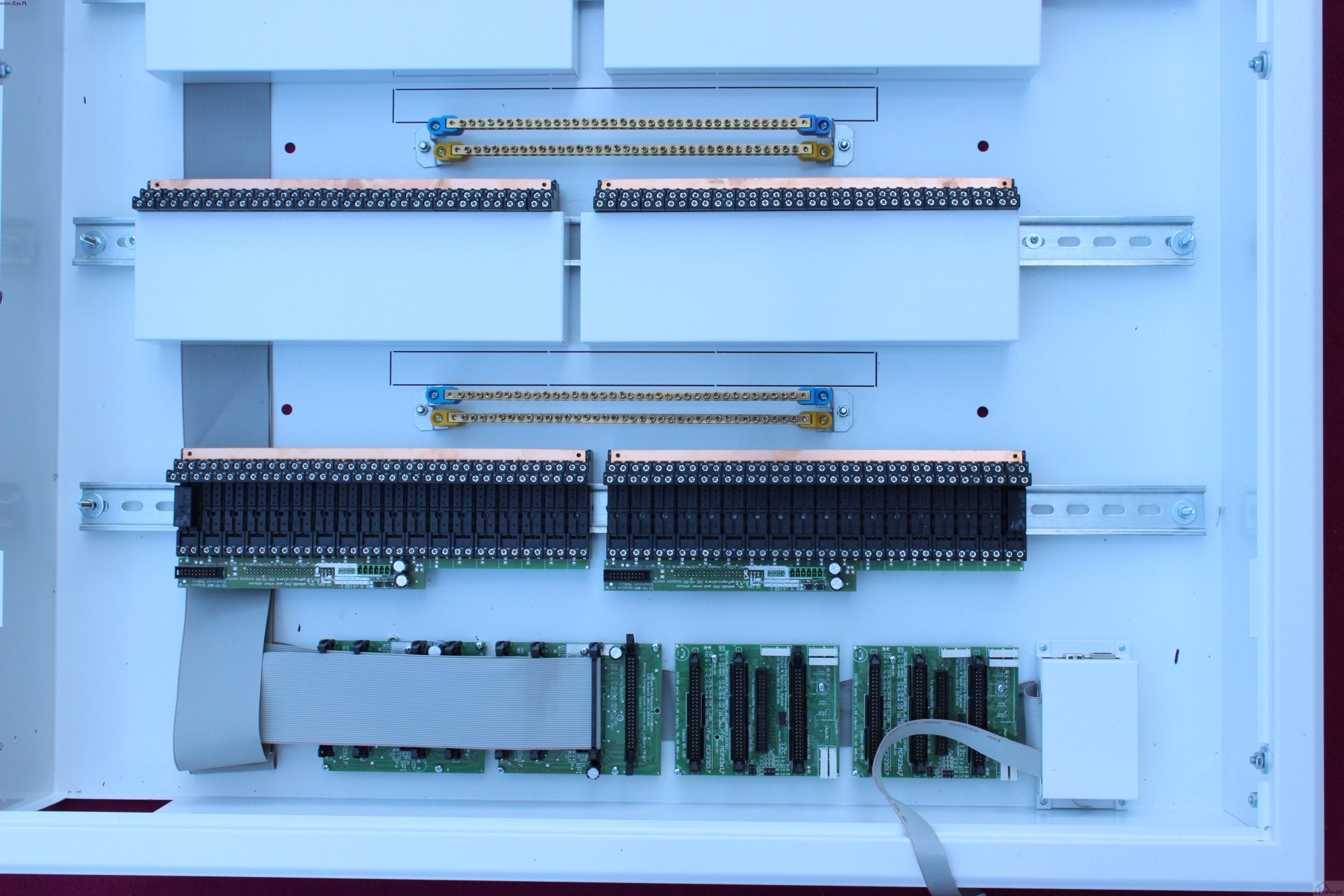

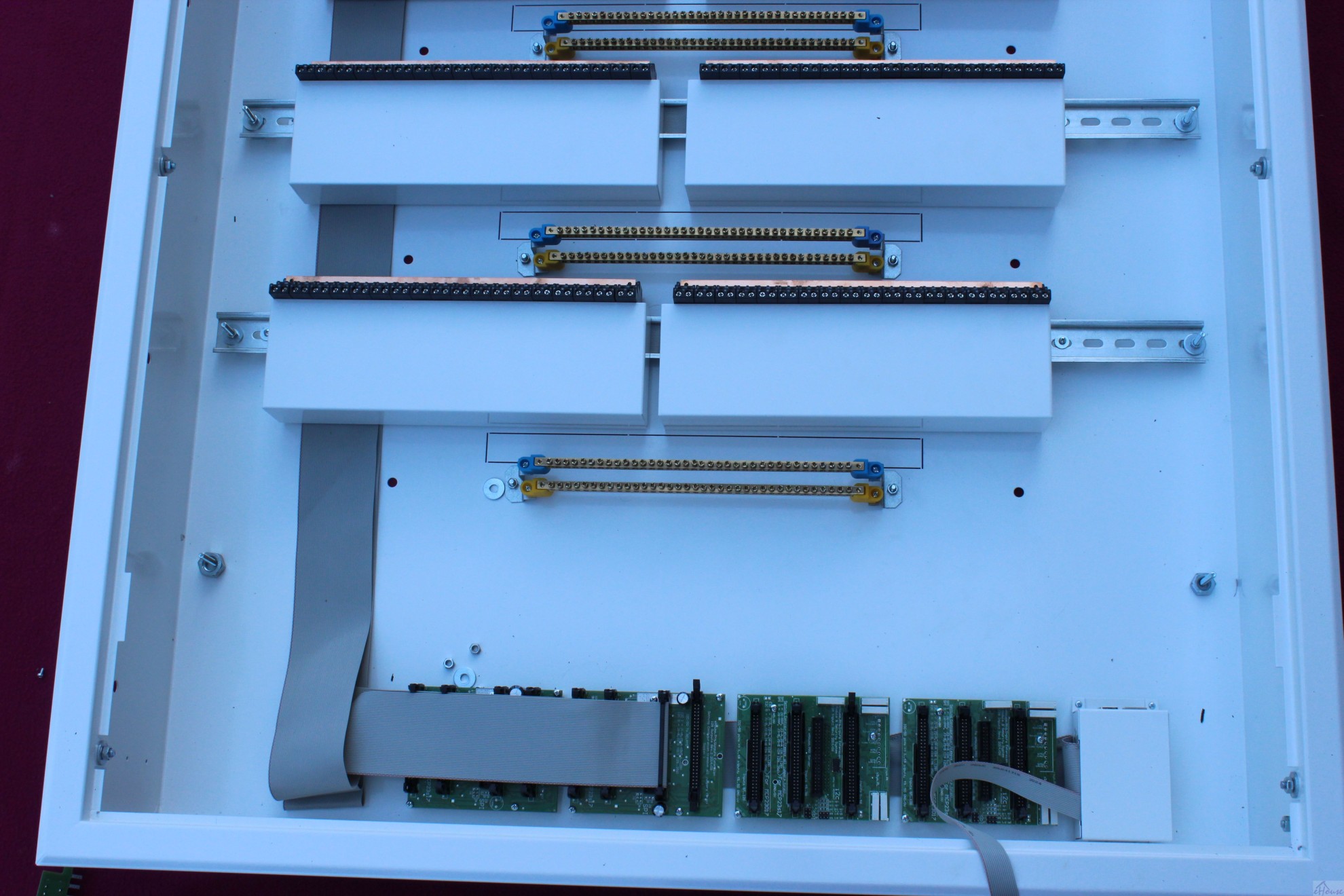
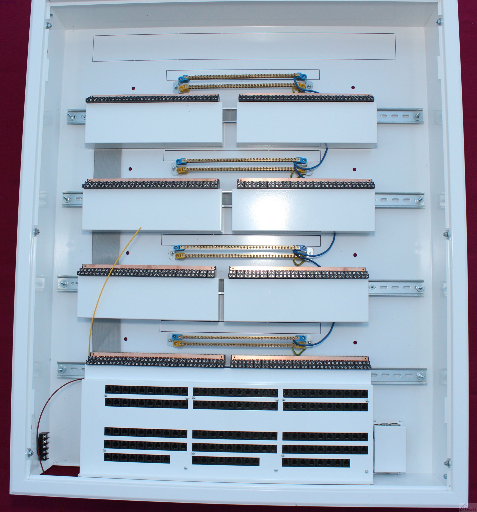
Then, shorts protective rail (yellow-green wire diameter 8-10mm2) to the nearest screws on the cover of the box.This applies to all protective rails.
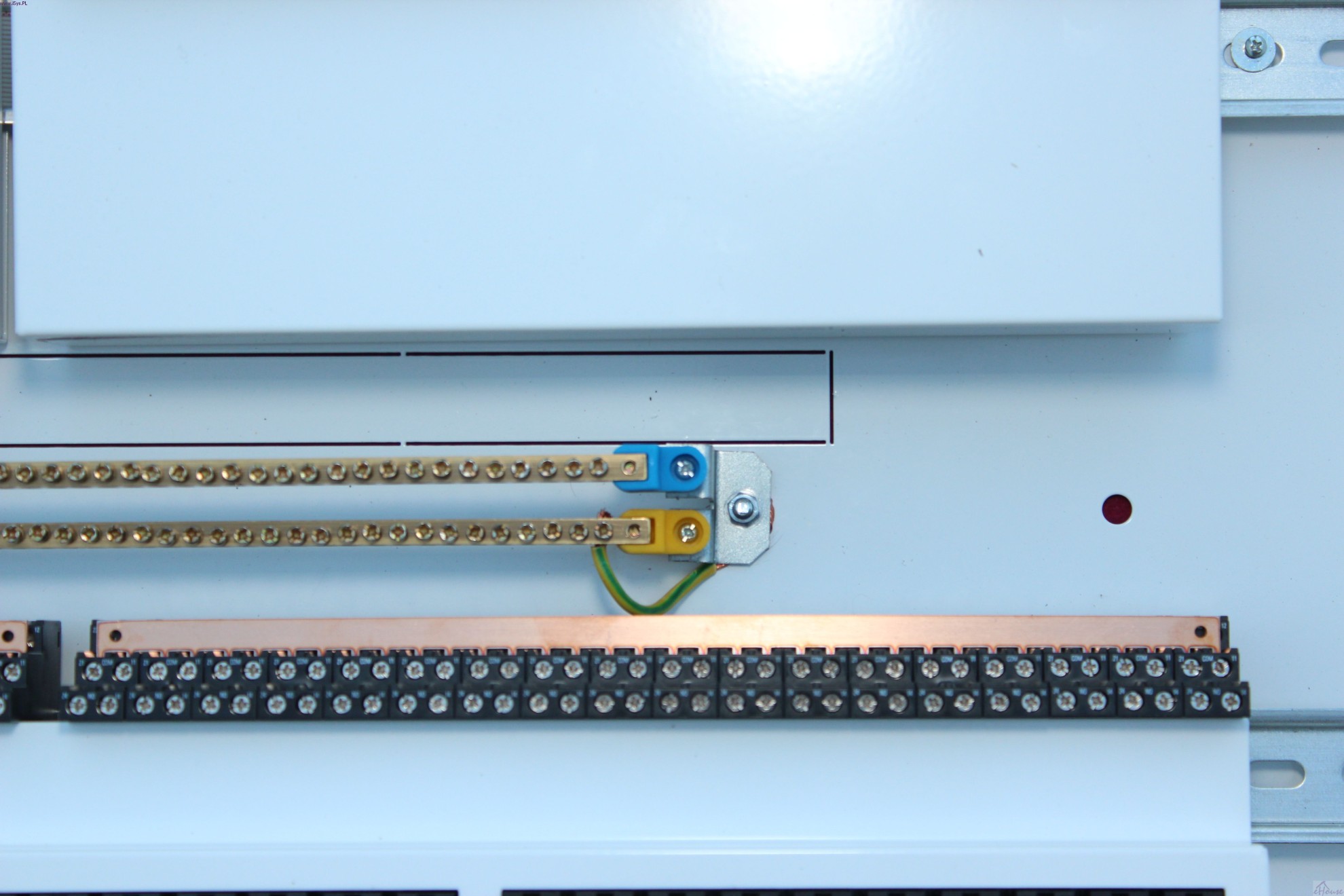
In the next step shorts all buses neutral (blue wire diameter 8-10mm2) if we do not use a residual current device fuses.
Otherwise neutral terminals connected to fuses residual current device.
You can apply one fuse-breaker for each DIN rail (exit 32) and safety relief for each bus.
Each rail can incorporate a different phase. COM Copper rails can be cut to switch between different voltage and phase relays on the module relays.
The free part of rails can be installed fuses residual current circuit breakers, redundant power supplies or other devices on the DIN rail.
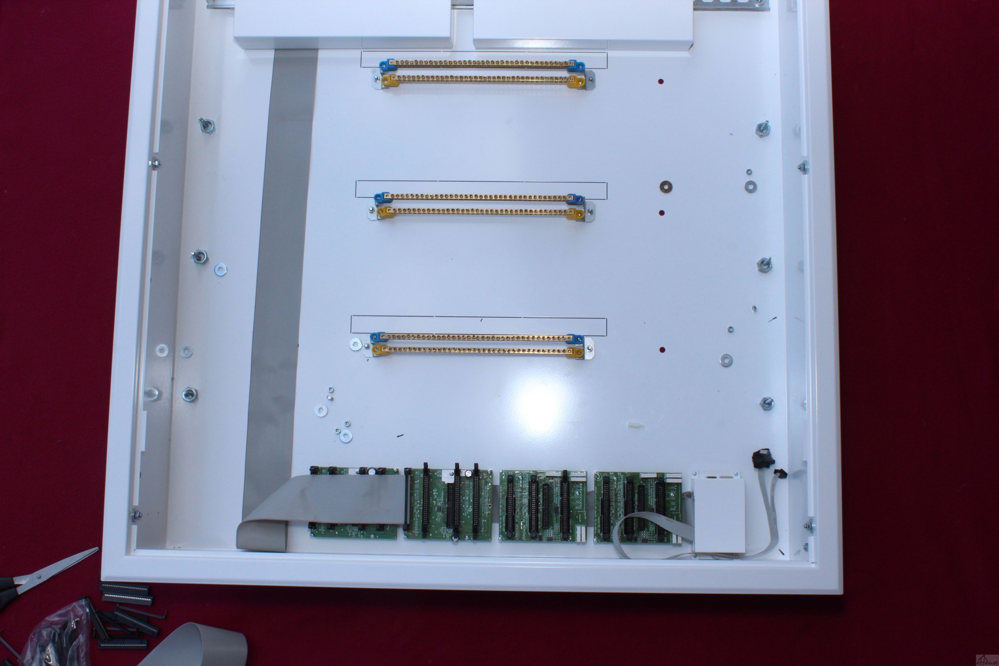
Modules “RJ-12 Input Expander” connects the power cord (from the top) in accordance with a photo. Yellow wire (+ 12V UPS) brown wire (0V). It is a power supply alarm sensors so it should be backed up with UPS for alarm and is not influenced by the lack power.
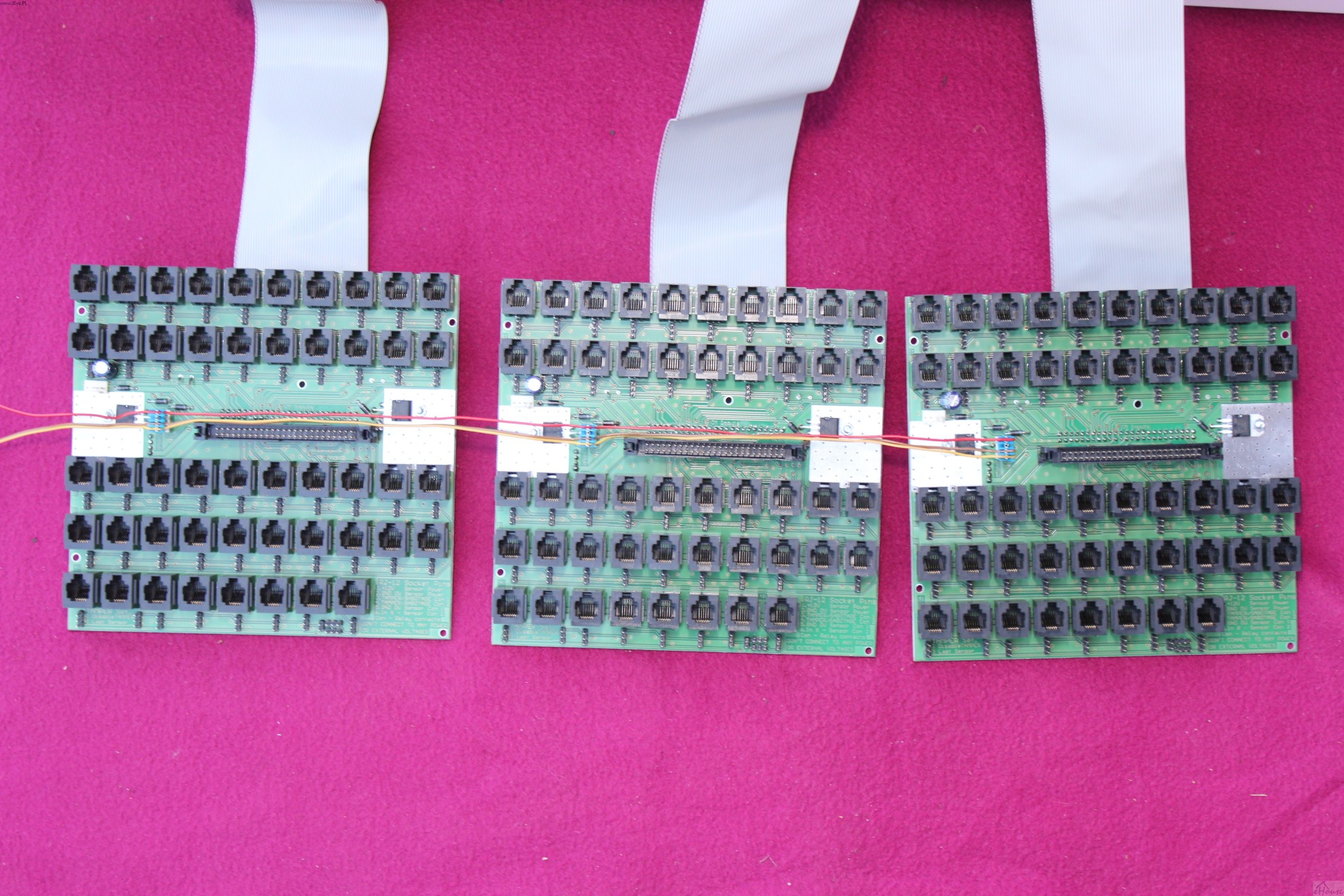
Then screw the modules of the control unit to enter the large bezel with the use of plastic spacers with a length of 15mm. On the side of the PCB be careful not to short tracks with screws, or you use insulation pads.
IDC-50 flat Tapes should be installed from underneath the PCB to not interfere with the installation of RJ-12.
The length of the tape respectively (70cm, 42cm, 42cm)
Connect flat tape to the input module (1-128).
When using 256 outputs and / or 256 Inputs also follow a flat strip, IDC-50 between I/O modules in the first box and relay modules and “control unit” flat, input RJ-12 to a sufficient distance (distance boxes). These distances are not critical, provided an additional power cord relays, mass, alarm sensors. You can install a second box of up to 30 meters from the first.
Particularly preferred is installed on the second floor.
A large hole at the bottom of the box (left side) is used to connect the tape flat IDC-50 to other switching and admission RJ-12 cables from alarm sensors and inputs.
Amateur and self-assembled central switching eHouse.PRO looks as professional as in the process of connecting the electrical box in factory.

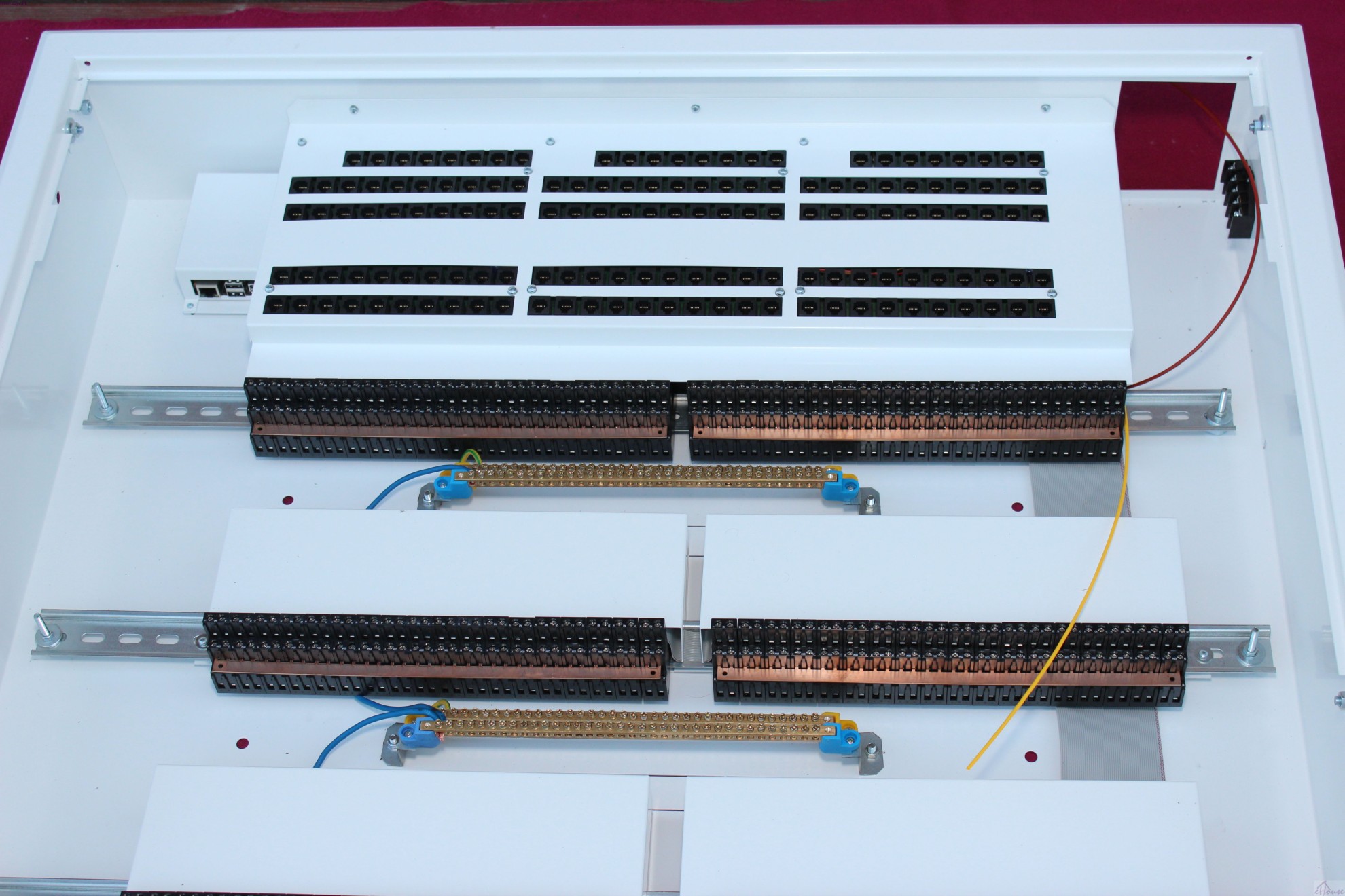
The view from the top of the box:
Visible rail 2*5 to connect a low voltage supply.
Visible LAN connector and USB microcomputer Linux.
View of the right side and fixing holes:
Three screws allow the assembly and disassembly of frames for plastering
View of the upper wall of the box:
see the openings for the installation of LED power supply 8A and holes to remove for admission to the distribution 230V cables
View of the left side and fixing holes:
Three screws allow the assembly and disassembly of frames for plastering.
A large length of the screws for DIN rail (35mm) allows them to install with a distance, if we wanted to let all the 230V wires from the top, and then under the DIN/TH rails .
BUY: Building Automation eHouse.PRO